Lost your password? Please enter your email address. You will receive a link and will create a new password via email.
Please briefly explain why you feel this question should be reported.
Please briefly explain why you feel this answer should be reported.
Please briefly explain why you feel this user should be reported.
Amechieneer is a platform where the questions can be answered, doubts can be cleared, knowledge can be self tested through relevant quizzes, interviews can be cracked easily by having a glance on previous interview experiences in Mechanical Engineering. Enjoy the learning.
What is the difference between mechanical seal and gland seal?
Feature Mechanical Seal Gland Packing Principle of operation Utilizes two opposing sealing faces that create a non-contact seal through hydrodynamic lubrication or face contact. Relies on the compression of packing material around a rotating shaft to prevent leakage. Leakage rate Minimal leakage, ofRead more
What is a mechanical seal used for?
Mechanical seals are used to prevent leakage between rotating and stationary parts in a wide range of applications. The mechanical seal in a pump prevents leakage of process fluid effectively by employing the following design principles. Seal Face Contact: Mechanical seals rely on precise contact beRead more
Mechanical seals are used to prevent leakage between rotating and stationary parts in a wide range of applications. The mechanical seal in a pump prevents leakage of process fluid effectively by employing the following design principles.
- Seal Face Contact: Mechanical seals rely on precise contact between two opposing seal faces i.e. stationary face and rotating face (they are considered as a primary sealing point between rotary and stationary parts), typically made from hard and wear-resistant materials like silicon carbide or tungsten carbide. These faces are carefully lapped to ensure a smooth, flat surface that promotes hydrodynamic lubrication and prevents leakage. Typically, mechanical seal faces are lapped to achieve a surface finish of Ra<0.2 µm or better. This level of smoothness ensures that the seal faces can maintain a tight seal while minimizing contact pressure and wear.
- Hydrodynamic Lubrication: As the pump shaft rotates, a thin film of fluid is formed between the seal faces due to hydrodynamic lubrication. This fluid film prevents direct contact between the seal faces, reducing friction and wear, and maintaining a tight seal.
- Spring Force: Mechanical seals employ springs or other mechanisms to maintain a constant force between the seal faces, ensuring proper contact and sealing even under varying pressure and thermal conditions. This spring force ensures that the seal faces remain in close contact, preventing leakage and maintaining sealing integrity.
See lessWhat is the difference between single and double mechanical seals?
Feature Single Mechanical Seal Double Mechanical Seal Number of seal faces One Two Buffer fluid No Yes Leakage potential Higher Lower because the backup Seal assists in preventing the leak in case of failure. Reliability Lower Higher because of having an extra layer of protection (i.e. back up seal)Read more
Why double mechanical seal is used?
Double mechanical seals are widely used in various industrial applications due to their superior sealing performance and enhanced reliability. Here are some of the primary reasons why double mechanical seals are preferred: Zero Emission Compliance: A single mechanical seal permits the leakage of proRead more
Double mechanical seals are widely used in various industrial applications due to their superior sealing performance and enhanced reliability. Here are some of the primary reasons why double mechanical seals are preferred:
- Zero Emission Compliance: A single mechanical seal permits the leakage of process fluids in the form of vapors, these vapors arise from the heat generated by friction at the primary seal face contact. But double mechanical seals offer a virtually leak-proof sealing solution, preventing the escape of hazardous or toxic substances into the environment. This is particularly crucial for applications involving volatile organic compounds (VOCs), hazardous chemicals, or other sensitive fluids.
- Higher Reliability and Safety: Even if one seal fails, the process fluid will not leak into the atmosphere. Thus, double mechanical seals provide an extra layer of protection against leakage, ensuring the safe operation of equipment and preventing potential environmental contamination. This redundancy is essential in critical applications where even a minor leak could have severe consequences.
- Extended Seal Life: The buffer/barrier fluid prevents the pumped fluid from reaching the outboard seal in case of a leak from the inboard seal, ensuring that the outboard seal remains clean and lubricated. Thus, double mechanical seals effectively manage the lubrication and cooling of the seal faces, extending their lifespan and reducing the frequency of seal replacements.
- Versatility for Challenging Applications: Double mechanical seals can handle a wide range of fluids, including high-pressure, high-temperature, corrosive, and abrasive fluids. Their ability to withstand demanding conditions makes them suitable for various industrial applications.
- Backup Seal in Case of Failure: In the event of an inboard seal failure, the outboard seal in a double mechanical seal configuration acts as a backup, preventing the leakage of the process fluid. This redundancy ensures continued operation and minimizes downtime in critical applications.
- Alternative Seal for Unstable Lubrication: Double mechanical seals can provide an alternative sealing solution when the process fluid itself is not suitable for lubricating the seal faces. This is particularly useful for handling gaseous media, viscous fluids, non-settling slurries, or fluids prone to hardening.
- Early Detection of Seal Failure: In some double mechanical seal designs, the buffer fluid can be monitored for leakage, providing an early indication of seal failure before it progresses to a catastrophic event. This early detection allows for timely maintenance and prevents potential damage to equipment.
See lessWhat are the differences between Single springs and multiple springs in mechanical seals?
Single Spring Multiple Spring Load Distribution: Single springs bear the entire force exerted on the seal faces, leading to uneven force distribution because of their singular structure. Load Distribution: Multiple springs can distribute the load more evenly, reducing the stress on each individual sRead more
What is the orthogonality principle in vibration?
Orthogonal means that two things are at right angles to each other. When we say two vectors are orthogonal, it means they're perpendicular, forming a 90-degree angle. This shows that these vectors are independent—they don't affect each other's movement. The vectors are completely unrelated or uncorrRead more
Orthogonal means that two things are at right angles to each other. When we say two vectors are orthogonal, it means they’re perpendicular, forming a 90-degree angle. This shows that these vectors are independent—they don’t affect each other’s movement. The vectors are completely unrelated or uncorrelated in terms of their direction. The motion of one vector does not interfere or interact with another vector. Hence, they can be evaluated or calculated independently since there is no relation between them.
Similarly, the modes or mode shapes in a vibrating body are said to be orthogonal because the shape and characteristics of one mode do not influence or interact with other modes. Hence, they can be evaluated independently and separately. This idea leads to what we call the mode superposition principle.
That’s why the off-diagonal elements of the decoupled equations of motion (decoupled using modal orthogonal property) are zero.
See lessHow do Centrifugal Fans Work?
Impeller Structure and Function: An impeller is a pivotal component within a fan, characterized by its rotation and a series of blades. The impeller's primary role is to transfer kinetic energy to the working fluid, assuming air as the working fluid in this context. Centrifugal Action: When the impeRead more
Impeller Structure and Function:
An impeller is a pivotal component within a fan, characterized by its rotation and a series of blades. The impeller’s primary role is to transfer kinetic energy to the working fluid, assuming air as the working fluid in this context.
Centrifugal Action: When the impeller undergoes rotation, centrifugal action comes into play. This centrifugal force propels the working fluid (air) away from the impeller, creating a radial outflow.
Kinetic to Static Pressure Conversion: As the air moves between the series of blades, the kinetic energy it possesses undergoes a transformative process. According to Bernoulli’s theorem, the flow through a gradually increasing cross-section leads to the conversion of kinetic energy or velocity into static pressure.
Cross-Sectional Expansion: Simultaneously, the circumferential gap between the blades widens radially, resulting in an increase in the cross-sectional area. This expansion contributes to the conversion process, enhancing the transformation of kinetic energy into static pressure.
Spiral Casing and Pressure Conversion: The air, still carrying some kinetic energy from the impeller, proceeds through the spiral casing. This casing is designed with a gradual increase in cross-section in the flow direction. As the air traverses this casing, the leftover kinetic energy transforms into static pressure.
Blade Tip Discharge and Vacuum Formation: Upon reaching the blade tip, the air is forcefully expelled from the impeller. This expulsion creates a gap or vacuum near the center of the impeller, termed the “eye” of the impeller. This eye becomes a focal point for suction, drawing in more air to continue the cycle.
In essence, the impeller’s rotation, in conjunction with the blade design and the principles of fluid dynamics, facilitates the conversion of kinetic energy into static pressure, ensuring efficient air movement within the fan. The suction created at the eye of the impeller is a crucial aspect of this process, contributing to the overall effectiveness of the fan system.
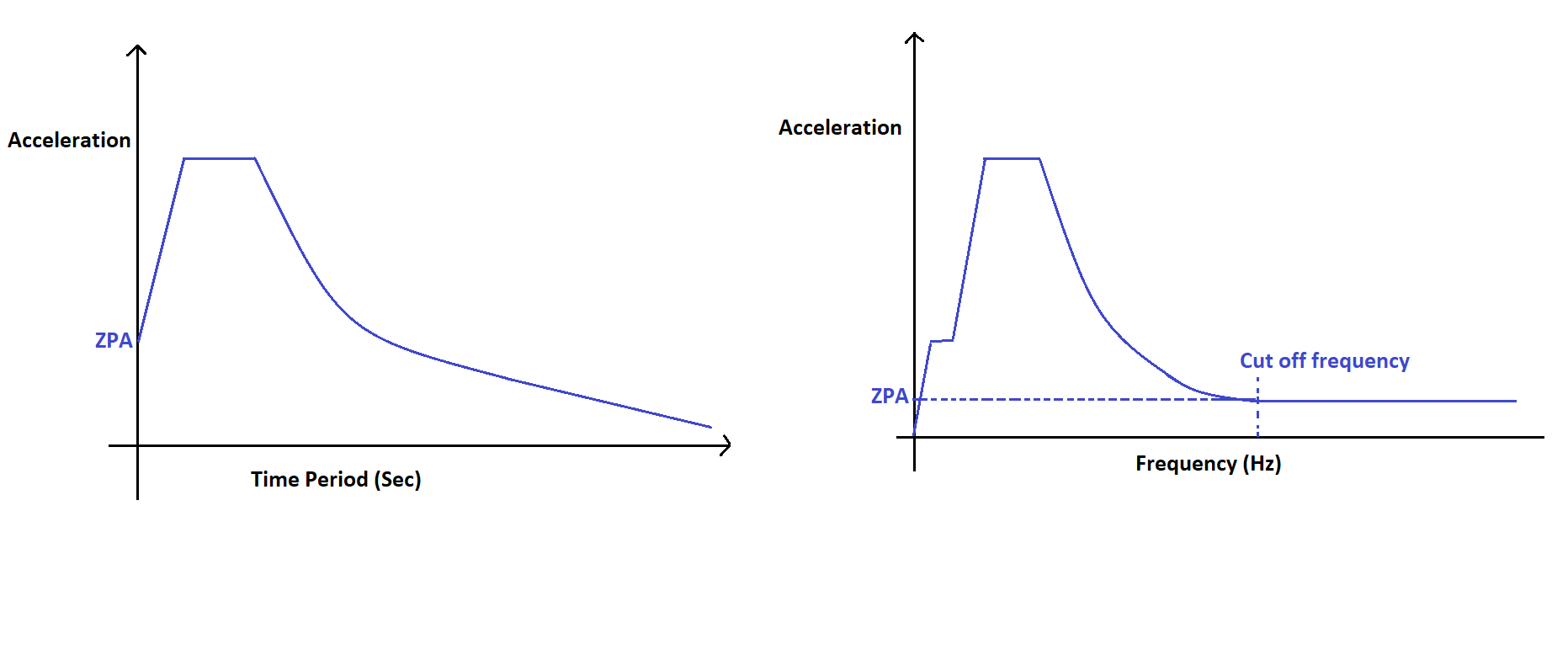
See lessWhat is Zero Period Acceleration (ZPA)?
Zero period Acceleration (ZPA) refers to the spectral acceleration of the zero-time period structure under earthquake excitation. In other words, the zero-time period structure means the structure has a very high natural frequency (i.e. f=1/T). Since natural frequency is proportional to $\sqrt (stifRead more
Zero period Acceleration (ZPA) refers to the spectral acceleration of the zero-time period structure under earthquake excitation. In other words, the zero-time period structure means the structure has a very high natural frequency (i.e. f=1/T). Since natural frequency is proportional to
 the structure having very high stiffness or a rigid structure will have a high natural frequency. ZPA has the value same as ground acceleration because if the structure is rigid, it will accelerate with the same magnitude of excitation acceleration.
See lessWhat is floor response spectrum?
The design response spectrum helps in analysing the seismic behaviour of the primary structure. However, it cannot be used for analysing the behaviour of the secondary structure or a component mounted in the primary structure. Because the base acceleration seen by a tank mounted on the second floorRead more
The design response spectrum helps in analysing the seismic behaviour of the primary structure. However, it cannot be used for analysing the behaviour of the secondary structure or a component mounted in the primary structure. Because the base acceleration seen by a tank mounted on the second floor of the primary structure is not the same as the original ground acceleration of a primary structure. The primary structure acts as a band pass filter because the primary structure will not excite to very low frequencies or very high frequencies as compared to its natural frequency. Hence the primary structure will allow the earthquake signals having a frequency content close to its natural frequency. The peak responses of a particular floor at a given elevation are related to the natural frequency of the primary structure. The response of the tank on floor-1 is not similar to that of the same tank on floor-2 of the same primary building. Hence the floor response spectra are developed for different floors of the primary structure. The floor response spectra are drawn in a similar manner as that of the design response spectrum by drawing the envelope over the peaks of past response spectra.
See lessWhat is the design response spectrum?
The response spectrum which is used for the seismic analysis of a new structure for an anticipated or upcoming earthquake. From the past seismological data of a particular location, a single response spectrum was drawn using a single earthquake signal alone cannot be used for analysing the behaviourRead more
The response spectrum which is used for the seismic analysis of a new structure for an anticipated or upcoming earthquake. From the past seismological data of a particular location, a single response spectrum was drawn using a single earthquake signal alone cannot be used for analysing the behaviour of new structures for future earthquakes. Because Earthquake – A having the peak ground acceleration amplitude at a certain frequency is never Similar to Earthquake – B having the same peak ground acceleration value at a different frequency. Hence no two earthquakes are similar to each other. The stresses induced in a building structure having a natural frequency closer to that of earthquake – A is higher as compared to the stresses induced in the same building structure due to earthquake – B which has a significant frequency component far away from the natural frequency of the building. To overcome this, the past 25 numbers of earthquake signals of a particular location are considered and their individual response spectrum is plotted in the same
 Vs frequency plot. The envelope drawn over the Peaks of all 25 Response spectra is called the design response spectrum. The number of previous earthquakes considered for plotting the design response Spectrum may vary from standard to standard. The design response spectrum curve is smooth in contrast to the spiky response spectrum as shown in the figure below.
The design response spectrum can be plotted in
 vs frequency plot or
  vs Time period plot as shown in the figure below.

See less