
Table of Contents
Interview Questions Part-3 (11 to 15)
11. What is the difference between a pipe and a tube?
| Pipe | Tube |
| The cross-section is always round in shape | The cross-sectional shape can be square, rectangular or cylindrical |
| Pipes are measured by nominal diameter (Diameter Nominal (DN) or Nominal Pipe Size (NPS)) and schedule number (i.e., wall thickness) Note: For the pipe size below 12” OD>NPS>ID. For pipe size greater than 14”, OD=NPS | Tubes are measured by the outer diameter and gauge number (i.e., wall thickness) |
Pipes are used for transporting fluids. Though NPS represents the mean diameter of the pipe, inner diameter is the key parameter for a pipe because it represents how much flow a pipe can transport through it.  | Tubes are preferred for structural applications like rollers of conveyor belts…etc. And most importantly in heat exchangers like shell and tube. |
| For the given DN or NPS, by increasing the schedule number, wall thickness increases by decreasing the inner diameter but the outer diameter remains constant. | Similarly, for a tube also, the OD remains the same whatever may be gauge number i.e., wall thickness. The wall thickness increases by reducing the ID but OD is kept constant. |
12. What is the difference between a struct and a column?
| Struct | Column |
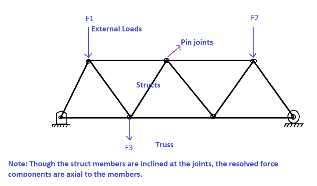
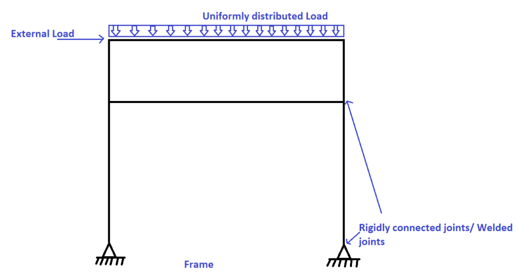
| A struct is a compressive member in a truss structure. Note: In a truss, members are free to rotate about the joints and carry only axial loads. | A column is a compressive member in a frame structure. Note: In a frame, members are rigidly connected (i.e., cannot be rotated freely about the joints) thus supports all types of loads. |
The ratio of effective length to diameter is less than 3 i.e.,  | The ratio of effective length to diameter is greater than 3 i.e.,  |
| Can support only axial loads | Can support axial & lateral loads and bending moments. |
| Loads are applied near joints only as shown in the following figure. | Loads can be applied anywhere as shown in the following figure. |
13. What happens when a crankshaft of a reciprocating compressor rotates in the opposite direction?
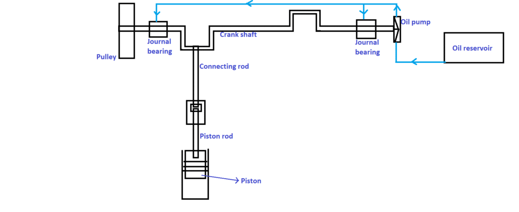
A piston is generally connected to the crankshaft with a piston rod and connecting rod in between, as shown in the following figure. Whatever may be the rotational direction of the crankshaft, the piston reciprocates to and fro. Based on the to and fro motion of the piston, the suction and discharge valve opens & closes. Thus, there is no difference in the intended operation of the reciprocating compressor.
But the main difference is,
The crankshaft is mounted on the hydrodynamic type journal bearings as shown in the following figure, i.e., the shaft levitates in the bearing under the oil pressure developed by a positive displacement type oil pump. The oil pump is connected directly to the crankshaft. If the crankshaft rotates in a reverse direction, the oil pump also rotates in a reverse direction. Thus, instead of supplying the oil to the journal bearings, the pump sucks the oil from the bearings resulting in the failure of bearings.
When a centrifugal oil pump is used instead of a positive displacement oil pump, the reverse rotation of the crankshaft causes the centrifugal oil pump to spin in the opposite direction. If a centrifugal pump has a backward curved impeller, it functions as a forward vane pump, but the fluid travels in the opposite direction through the volute casing, as illustrated in the image below.
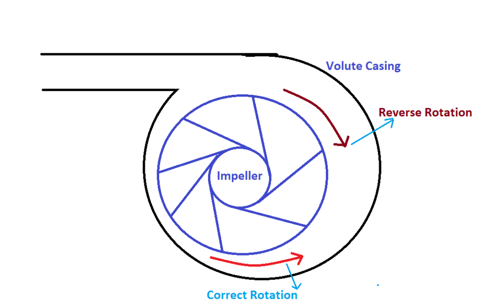
When the liquid flows in the opposite direction, the volute casing works as a nozzle rather than a diffuser. As a result, rather than being transformed into pressure energy, the kinetic energy of the liquid rises. As a result, the pump discharges the flow with less developed pressure, which is insufficient to levitate the shaft in hydrodynamic bearing, resulting in premature wear of journal bearings.
14. What is the difference between a fan and a blower?
| Fan | Blower |
Ratio of discharge pressure to suction pressure is less than 1.11 i.e.,  | Ratio of discharge pressure to suction pressure is in between 1.11 to 1.20 i.e.,  |
| The pressure rise is less than 1136 mm Wg. Note: mm Wg means millimeter of water gauge. | The pressure rise is in the range of 1136 to 2066 mm Wg Wg i.e., 0.1 bar to 0.2 bar |
15. Why are E309 electrodes preferred for welding SS 304L base metal to Mild steel base metal? (It means why the electrode of higher chemical composition as compared to both the base metal is chosen)
It is a dissimilar metal welding since both the base metals are of different chemical compositions. Have a look at the chemical composition below.
| Element | SS304L | E309 | Mild steel |
| Carbon | 0.03 % by wt | 0.15 % by wt | 0.15 % by wt |
| Nickel | 8 % by wt | 12% by wt | 0.65 % by wt |
| Chromium | 18 % by wt | 22% by wt | 1.25 % by wt |
As per the above-shown chemical composition, since welding involves very high temperatures (i.e., up to the state of molten metal) due to differences in the concentration of different elements, diffusion occurs from high concentration to low concentration resulting in the dilution of weldment, i.e., weld joint.
As per the chemical composition given in the table, locations of mild steel, SS 304L and E309 were plotted in the Schaeffler diagram as x,y and z, respectively, as shown in the following figure.
Note: Schaeffler diagram is an essential tool to predict the weld constituent in stainless steel base metal.
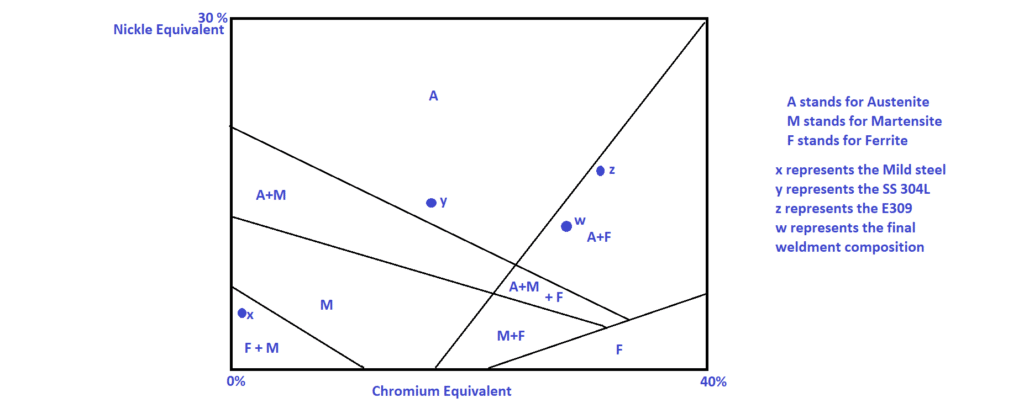
Any reduction in Chromium and Nickle content of the weldment results in the formation of martensitic structure in the weldment. The martensitic structure is highly brittle, resulting in early failure of weld joint when subjected to tensile loading. As per Schaeffler diagram, to achieve austenitic structure, the filler metal or the electrode having higher Nickle and Chromium content should be selected such that even after weld dilution, the resultant structure of weldment is of austenitic phase (i.e., plotted as w in the above figure).