Table of Contents
Introduction
The gas pressure increases by increasing the number of molecular collisions per unit of time—the number of collisions increases by following three principle ways.
- By increasing the number of gas molecules
- By increasing the kinetic energy of gas molecules by raising the gas temperature i.e.,
 or physical impaction on gas molecules by a moving object like an impeller
 - By reducing the volume of the container
Reciprocating or positive displacement compressors work on principle-3. Side-channel blower utilizes principle-2, i.e., the impeller adds the kinetic energy to the entrapped gas between the impeller’s blades.
Construction
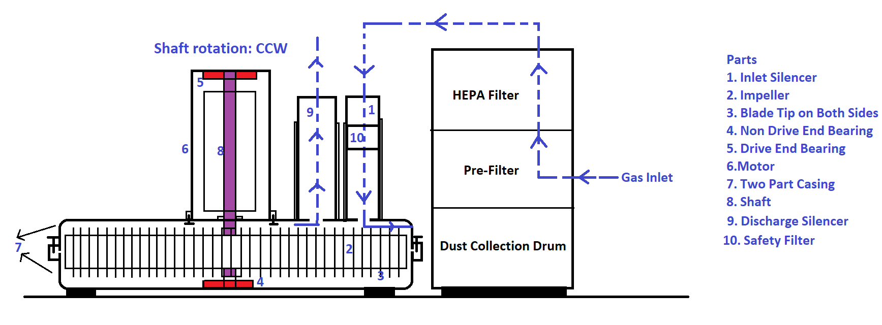
It consists of the following parts
- Pre-Filter
- HEPA Filter
- Safety Filter
- Inlet Silencer
- Impeller
- Two-part Casing
- Motor
- Bearing
- Exhaust Silencer
Why the Side Channel Blowers is called in different names?
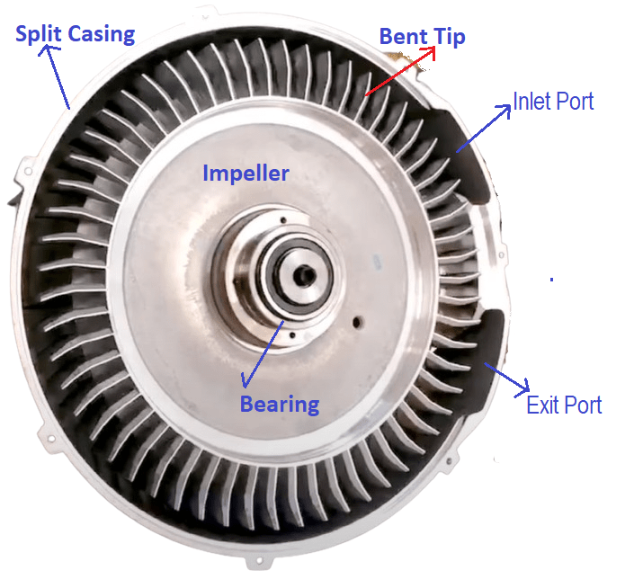
The side channel blower is also known as Vortex or Ring or Side Channel Blower. The impeller is directly mounted to the motor shaft and enclosed in a two-part housing, i.e., split-type casing, as shown in the above figure. The suction and discharge ports are on the sides of the impeller casing, hence the name side channel blower. Impeller casing is also known as a channel. But in centrifugal blowers, the suction is concentric to the impeller, and discharge is tangential to the casing. The side channel blower casing is of torus shape, i.e., the structure and cross-section are circular. Centrifugal blowers have a volute casing, i.e., casing cross-sectional area increases towards the path of working fluid resulting in the conversion of kinetic energy into pressure as per Bernoulli’s theorem. But the cross-section of the side channel blower is constant like a ring hence the name Ring blower. At the periphery of the impeller, carved blades are on both sides. The straight blades are curved slightly at the tip towards the rotational direction as shown in the figure-1a to impart circulation to the air leaving the blade. In general, the casing and the impeller are made of die-cast aluminium.
Working Principle of a Side Channel Blower
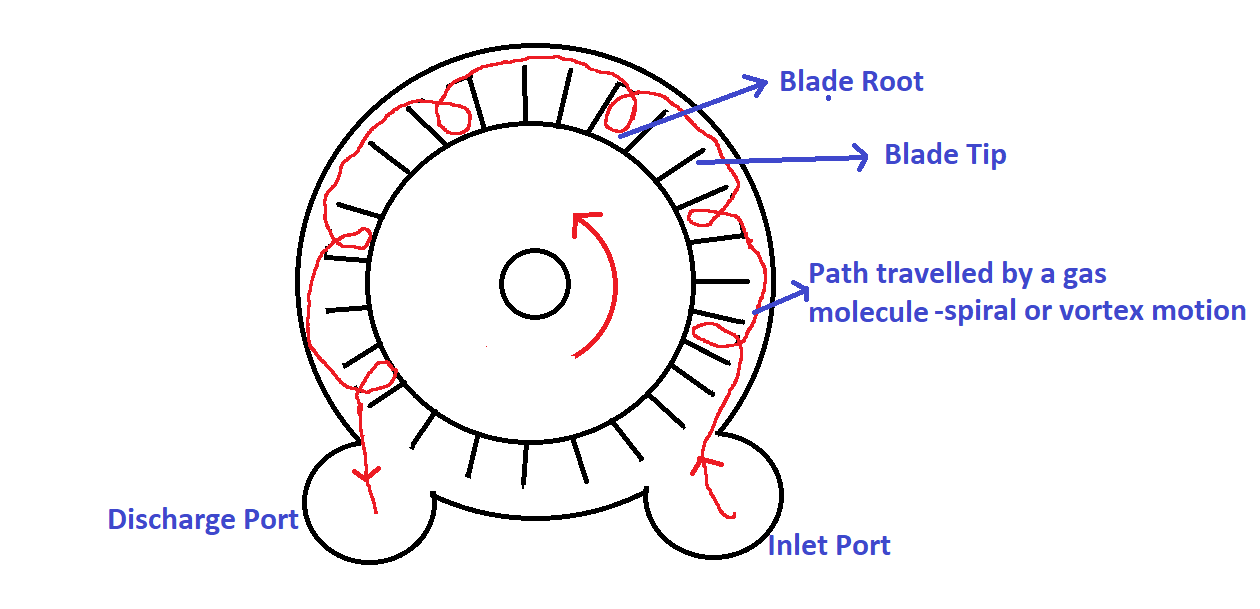
The Side Channel blower, also known as a regenerative blower, operates by repeatedly channeling air through its impeller. The impeller, equipped with several blades at its edge (as shown in following figure), creates chambers that trap the air. The space between two consecutive blades is called chamber. As the impeller spins, the centrifugal force pushes the trapped air outwards and hits the torus shaped casing. Because the blade’s tip is bent (see figure-1a) in the direction of rotation, the air exiting the blade tip flows in a circular motion in the direction of impeller rotation (see figure-2). The air hits the casing and comes back to the base of the next blade, as shown in the figure 2, resulting in recirculation hence called vortex blower. The curved shape of the blades directs the compressed air into the next chamber, where the process repeats, compressing the air further. This cycle allows the air to pass through multiple chambers in one rotation, continually gaining energy at each stage. This mechanism achieves multi-stage compression within a single revolution of the impeller. This type of blower is also known as regenerative blower because when the air passes through each and every chamber, it gets compressed progressively, thus energizing the air continuously, hence the name regenerative.
Operation of a Side Channel Blower
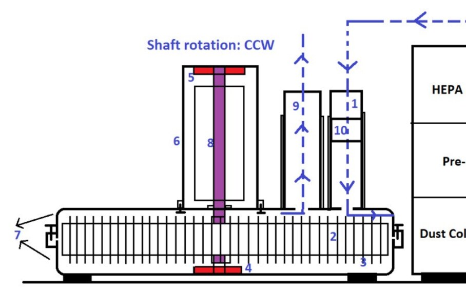
Between the blade tip and the casing, the radial gap ranges from 0.5mm to 1mm. A gas containing foreign particles of the appropriate size might cause the impeller to clog. Suction line filters filter the gas and remove foreign particles to reduce impeller jamming failure. At first, the gas enters through the pre-filter where the particle size greater than the 1-to-10-micron range is filtered. Secondly, the gas enters through the HEPA filter, and it filters the particle size greater than 0.3-micron size with a theoretical efficiency of 99.97%. Finally, the gas enters through the safety filter before entering the casing.
As the impeller starts rotating, a vacuum creates in the inlet port. The inlet port consists of an inbuilt silencer for noise cancellation. Then the gas molecules get trapped between the blades, and centrifugal force pushes them away from the blade root to the blade tip. Since the blade tip is slightly bent in the direction of rotation, the gas molecules travel a circular route in the same direction as the impeller spinning and collide with the casing, as shown in figure-2. Again, the gas molecules track back to the root of the next blade. The same pattern repeats till the gas reaches the discharge port. Every time the gas hits back to the blade root, the impeller imparts kinetic energy to the gas molecules; hence, gas molecules are accelerated repeatedly, increasing the collisions and resulting in pressure build-up.
Do’s and Don’ts in a Side Channel Blower
- Since the radial gap between the blade tip and casing is minimal, the side channel blower develops the pressure with minimum slippage. If the discharge valve is closed while the blower is in operation, it can cause physical damage due to discharge pressure. But in a centrifugal type of blower, due to the good amount of radial gap between the impeller and casing, the gas slips and undergoes churning action hence the extent of damage is negligible.
- Throttling of the suction or discharge valve of the side channel blower results in increased collision of gas molecules, and its temperature rises, causing the impeller and casing to undergo thermal expansion. Thus, the impeller and casing should be made of the same material to achieve uniform thermal expansion resulting in a constant gap between them.
Application
Side channel blowers are predominantly used in the seed transfer system. The seed might be sand or granular powder particles. Its distinguishing feature from other blowers is the lack of direct contact between the feed and the impeller. The details are displayed in the image below.
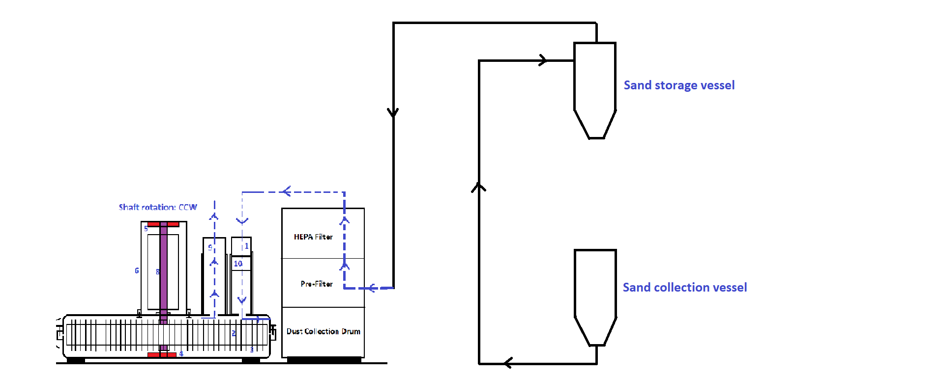
The sand storage vessel is maintained under a vacuum using a side channel blower. Thus sand in the sand collection vessel transfers to the storage vessel without direct contact with the impeller.
Thermal Protection
Since the gas molecules undergo several collisions before leaving the outlet port, the discharged gas is at a high temperature. Hence thermal protection for the motor is mandatory to avoid motor failure once the temperature crosses the operating limit.
Advantages of Side Channel Blower
- Compact because the vacuum unit and the motor are in a single unit.
- Maintenance-free because the impeller and shaft are the only rotating parts.
- Vibration-free because the blower does not have many rotating parts and there is no alignment issue between the driver and driven system to create vibration due to misalignment since the impeller is mounted directly to the motor shaft.
- Noise-free because of integrated silencers located at the inlet port and outlet port of the blower.
