Table of Contents
Rotary Airlock Valve (RAV)
A Rotary Airlock Valve (RAV) locks or prevents the movement of air or gas from one system to the other while maintaining the flow of material through it. In general, a rotary airlock is used to discharge bulk solid materials like coarse or fine powder & cake in the chemical process industry, granules in the cement industry…etc. A rotary airlock valve is also known as a rotary feeder.
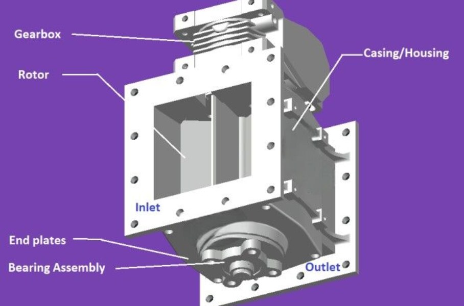
Parts of Rotary Air Lock Valve
- Housing
- Rotor
- Endplates
- Bearing
- Seal (gland Packing)
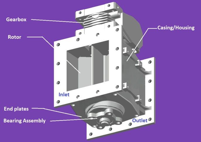
Rotary Airlock Valve Working Principle
A rotary airlock valve consists of a rotor on which blades or grooves are attached. Let us assume P1 is the high-pressure system and P2 is the vacuum system as shown in the below figure.
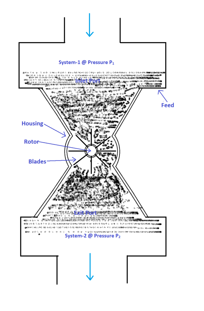
The material from system-1 at pressure P1 enters through the inlet port and gets filled in the pockets (i.e., the gap between the blades). When the rotor rotates, the material transfers to system-2 at pressure P2 through the exit port by maintaining the constant pressures P1 and P2 in system-1 and system-2 respectively. Material discharges from the rotor with the help of gravity.
The airlock is achieved by maintaining a tight clearance between the blades and housing. Thus, the rotary airlock valve locks the movement of air between the inlet & exit ports while transferring the material through it. Hence RAV acts as a separator between a high-pressure system and a low-pressure system.
A larger pocket size is best suited for transferring the sticky materials since more material can accommodate the larger pocket, material becomes heavy enough that it falls easily from the pocket due to gravity without getting stick to the rotor. By controlling the speed of the rotor, a metered quantity of material flow can be achieved since a fixed volume of material fills the pocket between the blades. Thus, the rotary airlock valve is also known as a rotary feeder.
Note-1 (Why it is called a Rotary Air Lock Valve?)
- Rotary: Because of the presence of the rotor.
- Airlock: Because the movement of air is locked through the RAV.
- Valve: Because it regulates or controls the flow of material through it.
Rotary Airlock Valve Troubleshooting
Possible Air Leakages in Rotary Air Lock Valve
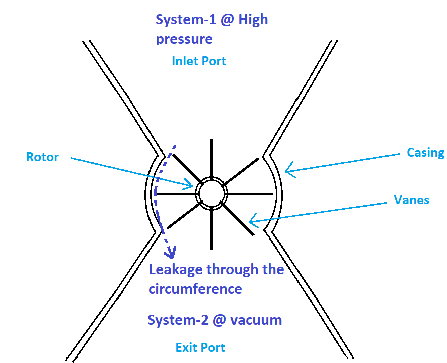
Clearance Leakage–1: Leakage through the circumference of the rotor
Air/gas leaks from system-1 to system-2 through the clearance between the blades and housing i.e., through the circumference of the rotor as shown in the following figure.
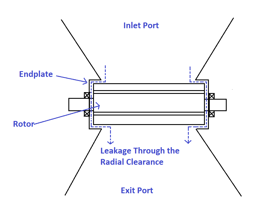
Clearance Leakage-2: Leakage through the radial clearance
Air/gas leaks through the clearance between the rotor and the end plates as shown in the following figure.
Note-2
For a given feed rate through the RAV, if the pocket size between the blades is large then the required speed of the rotor will be low thus the wear and displacement leakage can be reduced.
Types of Rotary Airlock Valve and its Applications
The rotary airlock valve is classified into the following types based on the type of rotor.
1. Closed-End Rotor
A disc is mounted perpendicular to the shaft and attached to both ends of the rotor as shown in the below figure.
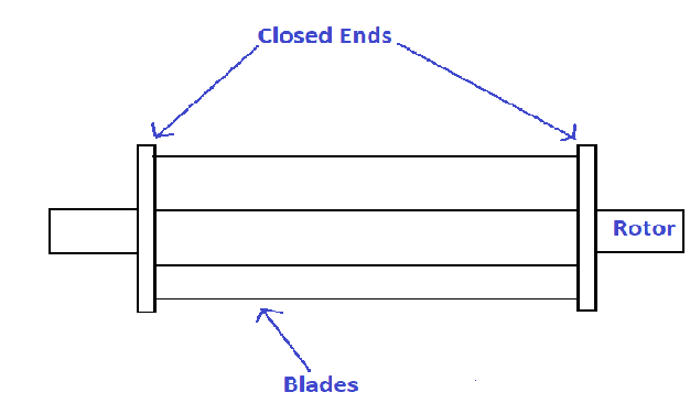
Application of Close End Rotor – Rotary Air Lock Valve (RAV)
A closed-end rotor is preferred when the material to be transferred is abrasive because the closed-end protects the end plates from abrasion by preventing the deposition of material between the blades and the endplates.
Air leakage is reduced between the blades and the endplates.
2. Open End Rotor
The rotor doesn’t have a disc at the end of the blades.
Application of Open End Rotor – Rotary Air Lock Valve (RAV)
The open rotor is preferred when the material to be transferred is non-abrasive because generally, the material escapes through the gap between the blades and the end plates resulting in wear.
3. Scalloped Rotor
The circumference of the rotor consists of a series of semi-circular grooves (called scallops) as shown in the figure below.
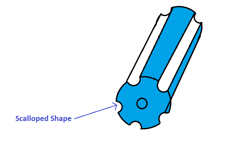
Application of Scalloped Rotor – Rotary Air Lock Valve (RAV)
A Scalloped-shaped rotor is preferred when the material to be handled is sticky because the scalloped shape does not contain any sharp corners for the material to get settled permanently. Instead, it has a curvy shape to ease the flow of material.
Rotary Air Lock Valve Specifications
The Rotary Airlock valve is specified by following operational parameters
- The pressure differential across the RAV (It represents the air loss through the RAV)
- Feed rate through the RAV (It represents the pocket size, RPM…etc.)
Rotary Air Lock Valve Clearance
The clearance between the rotor and housing in a rotary air lock valve is typically very small, ranging from 0.003 inches (0.08 mm) to 0.009 inches (0.23 mm) for standard valves. However, this clearance can vary depending on several factors:
- Valve size: Smaller valves tend to have tighter clearances. Because smaller valves deal with smaller volumes of air and often operate at lower pressures. To achieve a good seal with a smaller sealing surface, the clearance between the rotor and housing needs to be minimal. Even a small leak can have a significant impact on the valve’s performance in a smaller system.
- Material being handled: Abrasive materials may necessitate slightly larger clearances to accommodate wear and tear.
- Temperature: Valves operating at higher temperatures may need slightly more clearance to allow for thermal expansion.
- Specific application: The rotary air lock valve might be designed for a specific purpose with a customized clearance.
Note: Minimal clearance is ideal for creating an effective airlock and minimizing leakage
Rotary Air Lock Valve Capacity Calculation
The capacity of a rotary air lock valve refers to the mass of material it can transfer per revolution. To calculate this capacity, you’ll need the following information:
- Volume of each pocket in the rotor: Assuming all the pockets are of the same size. Just multiply the area of the pocket by its length to get the volume (
 ) of each pocket.
 - Number of pockets (n): Total number of pockets in the rotor.
- Product Density (D): This is the density of the material, measured in units of mass per unit volume (e.g., pounds per cubic foot, kilograms per cubic meter).
- Rotor Speed (S): This is the number of revolutions the rotor completes per second.
Here’s the formula for calculating the rotary air lock valve capacity (C):
![]()
FAQ about Rotary Air Lock Valve
What are the common issues associated with Rotary Airlock Valves?
Common problems include rotor wear, air leakage, and material blockages.
Rotor Wear: This can be avoided by the proper selection of rotors and choosing the right material for the construction of the rotor and casing.
Air Leakage: It can be prevented by maintaining the close clearance between the rotor and casing.
Material Blockage: Sticking feed material to the vanes or grooves of the rotor can be a major issue. It can be prevented by applying non-stick coatings like PTFE on the rotor surface.
