Table of Contents
Introduction
This article discusses the construction, working principle, real-world applications, drawbacks, and basic calculations regarding Roots Blower.
Construction of Roots Blower
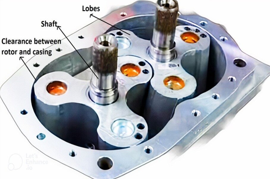
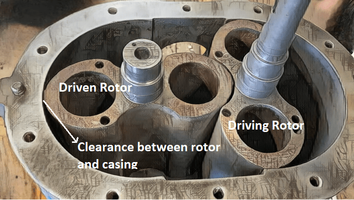
A Roots blower is a positive displacement blower featuring a pair of identical symmetrical rotors, illustrated in Figure 1. These rotors consist of shafts and lobes enclosed within an oval casing. One rotor serves as the driver, and the other is driven, operating without physical contact. A micron-level clearance is meticulously maintained between them, with support from bearings.
Both rotors intermesh through identical gears, rotating synchronously but in opposite directions. These rotors are crafted from Grey Cast Iron, known for their exceptional attributes, including high stiffness, machinability, vibration dampening, and excellent heat capacity and thermal conductivity characteristics.
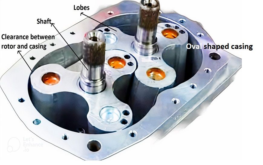
Roots Blower components
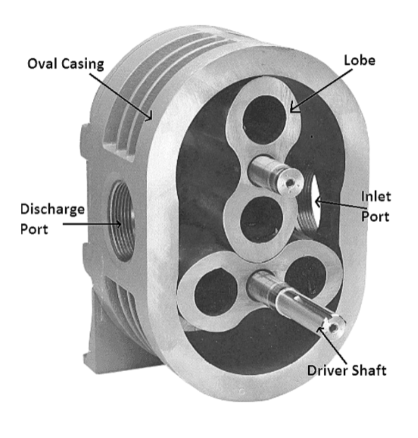
Roots blower contains the following components.
- Lobes
- Casing
- Inlet Port
- Outlet Port
- Shaft
- Bearing
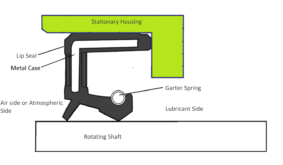
- Seals
Clearance Between the Rotor and the Casing of Roots Blower
In general, the optimum clearance between the rotor and the casing of the Roots Blower is in the range of 100 to 200 Microns as a compromise between wear and volumetric efficiency.
Why it is called Roots Blower?
Roots is the name of American inventors Philander and Francis Marion Roots who invented the blower in the late 19th century. That’s why the letter “R” in the word “ Roots” is seen in capitals.
Working Principle of Roots Blower
As the rotor inside the casing rotates, it makes spaces or pockets. These pockets grab air from the inlet port, keep it between the lobes (the rotating part) and the casing (the stationary part), and then push it out through the exit. But you might be wondering, where does the air get squeezed or compressed?
Actually, the rotors themselves don’t directly compress the gas in a Roots blower. Here’s why:
In a blower, the difference in pressure between the air at the inlet and the air at the outlet is relatively small, unlike in a compressor where the pressure difference can be much higher.
Now, there’s a very close space, usually just a few microns to a few millimetres wide, between the rotors and the casing to prevent wear and reduce noise. Because of this small gap, the high-pressure air that’s being pushed out tries to flow back into the inlet due to the pressure difference. This happens until the pressure inside the blower equalizes.
This backflow of air through the small gap between the rotor and the casing is what causes the air to get compressed in an irreversible manner, and as a result, the pressure at the outlet increases.
Do’s and Don’ts – Roots Blower
If the Roots blower is allowed to run beyond the rated specifications i.e. higher speeds, the heat generated due to excess compression leads to thermal expansion of rotors that results in jamming of rotors due to a reduction in clearance between the rotor and the casing.
Roots blowers have higher volumetric efficiency when allowed to run at a moderate compression ratio. In general, available capacities of single-stage Roots blower ranges from 10 ![]() to 10,000
to 10,000 ![]() and pressures up to
and pressures up to ![]() .
.
Note: Rotor containing three lobes has relatively less leakage that is due to backflow as compared to twin lobe blower thus reducing the power consumption.
Applications of Roots Blower
Roots blowers are preferred mainly where steady and consistent flow with low discharge pressures are required.
- Aeration: To provide oxygen to wastewater treatment basins, aquaculture systems, and other industrial processes.
- Combustion air supply: To supply air to boilers and other combustion systems.
- Vacuum drying: To create a vacuum in chambers where products are dried.
- Fume extraction: To extract fumes from industrial processes.
- Dust collection: To collect dust from industrial processes.
- Sewage treatment: Roots blowers are used to aerate wastewater and provide oxygen to microorganisms that break down organic matter.
- Water treatment: To oxygenate water and remove impurities.
Roots Blower Types
Roots blower is classified based on the number of lobes in the rotor and the type of rotors used. Primarily there are two types of Roots blower based on the number of lobes. They are
- Two lobe Roots blower
- Three lobe Roots blower
Two-Lobe Roots Blower
- It features two lobes and these lobes have symmetrical, identical profiles.
- The two-lobe design provides a balanced operation but can have some internal leakage. The lobes have symmetrical, identical profiles, and they rotate closely together. This symmetry means that there is a more direct path for air or gas to escape between the lobes, creating internal leakage.
Three-Lobe Roots Blower
- Three-lobe Roots blowers have three lobes per rotor. This design is sometimes called a tri-lobe blower.
- The three-lobe configuration reduces pulsation in the air or gas flow, making it ideal for applications where a more consistent and low-pulsation airflow is required.
- Three-lobe Roots blowers are often used in applications where noise and vibration control are critical.
Roots blower classification based on the type of rotors. There are two types of rotors employed in Roots blower. They are
- Straight Lobes
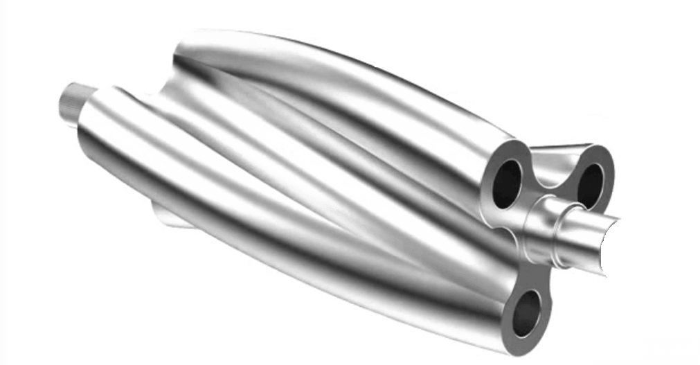
- Twisted Lobes
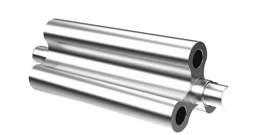
Advantages of Twisted Lobes over Straight Lobes
Reduced Pulsation:
Twisted lobes help in reducing the pulsation in the air or gas flow generated by the Roots blower. This is because twisted lobes enhance the volumetric efficiency of the Roots blower compared to straight lobes. This means that a larger percentage of the trapped air or gas is effectively moved through the blower without leakage. This reduction in internal leakage means there’s less backflow and turbulence within the blower, which, in turn, reduces pulsation.
Volumetric Efficiency Improvement:
Twisted lobes enhance the volumetric efficiency of the Roots blower compared to straight lobes. Because twisted lobes are designed with a helical or spiral shape. The helical shape reduces air leakage between the lobes and the casing, increasing the volumetric efficiency of the blower. This helical configuration means that the lobes are twisted along their axis as they rotate. This twist creates a progressive sealing action between the lobes and the casing.
Lower Noise and Vibration:
Twisted lobes also contribute to lower noise and vibration levels compared to straight lobes. The reduced pulsation and smoother operation result in a quieter and less vibration-prone blower, making it more suitable for noise-sensitive environments.
Roots Blower vs. Centrifugal Blower
| Characteristic | Roots Blower | Centrifugal Blower |
|---|---|---|
| Operating Principle | Positive displacement blower with counter-rotating lobes. | Kinetic energy transfer via impeller rotation. |
| Flow Type | Provides a constant flow with minimal pulsation irrespective of upstream resistance. | Provides a more uniform flow with higher pressure. Flow varies according to the upstream resistance. |
| Pressure Range | Low to moderate pressure applications. | Medium to high-pressure applications. |
| Efficiency | Typically less efficient than centrifugal blowers. Because air is mechanically trapped between the lobes and then displaced. This mechanism can lead to energy losses due to internal leakage, friction, and heat generation as the air is compressed. | Generally, more efficient because it uses kinetic energy to increase air pressure, which is often a more efficient process. |
| Air Compression | Uses mechanical compression as air is trapped and moved between lobes. | Uses kinetic energy to increase air pressure. |
| Noise and Vibration | Tends to be noisier and generates more vibrations. | Typically quieter and generates fewer vibrations. |
| Sealing Efficiency | Can have some internal leakage between the lobes and casing. | Minimal internal leakage. |
| Energy Consumption | May consume more energy for the same airflow. | Generally consumes less energy for the same airflow. |
| Flow Control | Not easily variable without additional equipment. | Flow rate is easier to control and modulate. |
| Applications | Aeration, pneumatic conveying, low-pressure industrial processes. | HVAC, industrial processes, high-pressure applications. |
| Size and Portability | Often bulkier and less portable. | More compact and easier to install. |
Roots Blower Performance Calculation
1. Inlet Volume or Inlet Capacity
![]()
Whereas
D stands for Displacement
N stands for Revolutions per Minute
Note: Because of clearance between the rotor and casing, high-pressure air back flows to the low-pressure side.
![]()
Slip is defined as the amount of air leaking through the clearance between the rotor and casing. Slip is represented in terms of Revolution Per Minute (N) that is required to compensate for the leakage. Slip_Application is determined by closing the discharge valve and rotating the rotor at a speed till the discharge pressure reaches 1 Psi.
2. Power Needed
![]() .
.
Since it is a positive displacement type blower, displacement per revolution is constant. Hence, the power required is directly proportional to the pressure rise in the system.
3. Temperature Rise of Air
![]()
Roots Blower Troubleshooting
| Problem | Possible Reasons |
| High motor current | 1. Discharge valve is in closed condition. 2. Running speed greater than the rated speed. 3. Incorrect Pressure Reducing Valve (PRV) setting (in case PRV is installed in discharge line). 4. Choked inlet filter. 5. Jamming of rotor. |
| High discharge temperature | 1. Higher system resistance. 2. Discharge valve in closed condition. |
| Jammed Shaft | 1. Jamming of rotors to the casing due to excess thermal expansion. 2. Deposition of foreign particles or rust between the rotor and the casing. 3. Jammed timing gears. 4. Faulty Bearings. |
| Excess vibration | 1. Unbalanced rotors. 2. Faulty bearings. 3. Structurally weak base. |
| Bearing Failure | 1. Over or under lubrication. 2. Excess belt tension (in case of belt-driven). 3. Excess vibration. |
Roots Blower Maintenance
Maintenance checks for a Roots blower are essential to ensure its smooth and efficient operation. Here are the key maintenance checks for a Roots blower:
- Lubrication:
- Check the blower’s oil level and ensure it is within the recommended range. (Recommended level: Fill the oil up to half portion of the sight glass)
- Verify that the lubricant is clean and free of contaminants. (Oil particulate analysis)
- Bearing Inspection:
- The condition of bearings can be readily assessed by measuring their vibrations.
- If the vibration is severe, examine the blower’s bearings for signs of wear, overheating, or unusual noise during operation.
- Check for proper lubrication of the bearings.
- Clearances:
- Verify that the clearances between the lobes and casing are within specifications.
- Any excessive clearances can lead to air leakage and reduced efficiency.
- Seal and Gasket Inspection:
- Inspect the seals and gaskets for wear, damage, or deterioration.
- Ensure that the seals are providing an effective barrier to prevent air or gas leakage.
- Bolt and Fastener Tightening:
- Check all bolts, nuts, and fasteners for tightness.
- Vibration during operation can cause these components to become loose.
- Air Filters:
- If the blower is equipped with air filters, inspect them for clogs and cleanliness.
- Clean or replace filters as necessary to maintain proper airflow.
- Drive Belt Inspection:
- For belt-driven blowers, check the condition and alignment of drive belts.
- Ensure proper tension and replace worn or damaged belts.
- Motor Check (if applicable):
- Inspect the blower’s motor for any signs of overheating or unusual noise.
- Verify that the motor is operating within its specified parameters.
- Alignment:
- Check the alignment of the blower’s components, including the lobes, shafts, and casings.
- Proper alignment is crucial for efficient operation.
- Vibration Analysis:
- Periodically conduct a vibration analysis to detect any unusual vibrations that may indicate problems with the blower.
- Temperature Checks:
- Monitor the operating temperature of the blower to ensure it remains within acceptable limits.
- Excessive heat can be a sign of potential issues.
- Pressure and Flow Verification:
- Ensure that the blower is meeting the performance requirements of the application by measuring the pressure and flow developed by the blower. Compare the results with the performance curve.
Performance Curve of Roots Blower
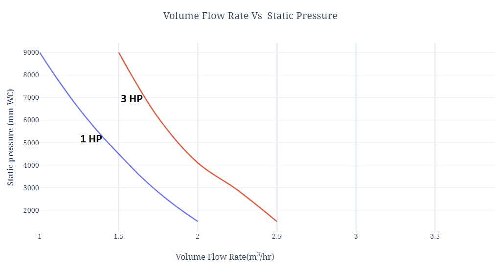
The following graph represents the performance of a typical Roots Blower utilized in pressurized applications instead of vacuum. As the discharge pressure increases, the volume flow rate through the blower reduces due to the backflow of high-pressure air through the clearance between the rotor and casing.
Roots Blower Specifications
The following represents the recommended specifications of Roots blowers:
- Type of service: Intermittent/Continuous
- Fluid Handled: Air/Gas
- Installation: Indoor/Outdoor
- Capacity or Rate of Discharge (
 )
) - Inlet Condition (Pressure/Temperature)
- Discharge Pressure (
 )
) - Differential Pressure (
 )
) - Proposed Operating Speed (RPM)
- Brake Horse Power At Duty Point (BHP)
- Recommended Motor (HP/ RPM)
- Discharge Flange size (mm)
- Proposed Discharge Line Size (mm)
- Orientation Flow: Horizontal / Vertical
- Oil Sealing Type: Lip Seal
- Lubrication for Pulley bearings: Grease Packed /Oil Filled
- Lubrication for Gear and its End Bearing: Grease Packed /Oil Filled
- Drive Type: V-Belt Drive
- Direction of Rotation of pulley: Clockwise or Anticlockwise
- Material of Construction
- Main Casing, Side:
- Plates & Rotor:
- Shafts :
- Gears (Must be Hardened & Ground)
