Table of Contents
Types of seals
The goal of the shaft seal is to seal the pressurized fluid at the contact between the rotating and stationary components. In general, there are two types of seals used to keep rotating shafts sealed. They are
- Radial seal
- Axial seal
1. Radial Seal
- As indicated in the following figure, the seal between the interface is established by two radially opposed cylindrical faces.
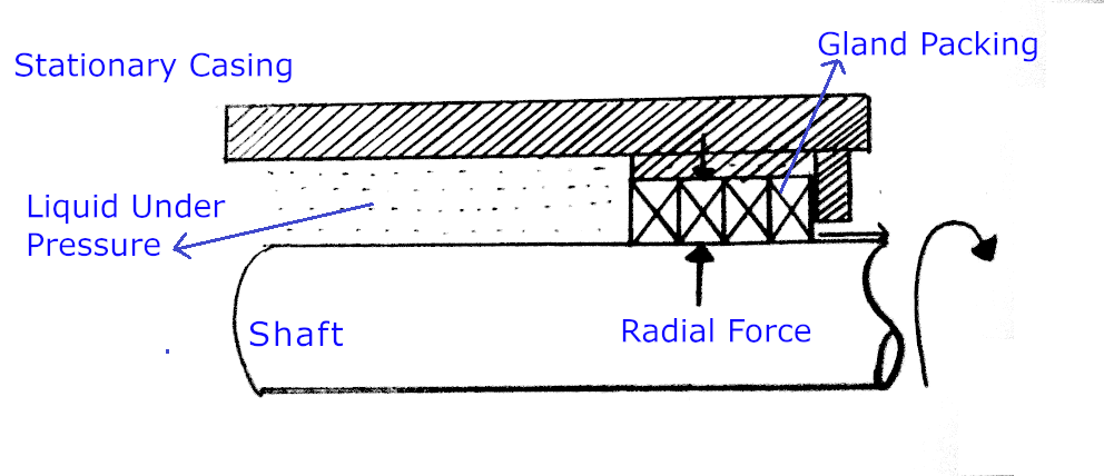
- A good example of a radial seal is gland packing in the stuffing box.
- In a radial seal, the leakage path is axial, that is, parallel to the shaft axis
2. Axial Seal
- As indicated in the following figure, the seal between the interface is established by two axially opposed plane surfaces.
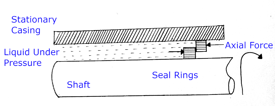
- An example of an axial seal is a mechanical seal.
- The leakage path is radial i.e., perpendicular to the shaft axis.
Difference between gland packing and mechanical seal
| Gland Packing | Mechanical Seal |
|---|---|
| It is a types of Radial seal | It is a type of Radial seal |
| Teflon or Graphite impregnated Teflon ropes are preferred to seal the interface between a rotary and stationary part | Leakage of process fluid in liquid form from a mechanical seal can be arrested completely. However, leakage in the form of vapour due to friction heat between rubbing faces is inevitable. |
| Liquid leakage through the gland packing is mandatory to dissipate the heat generated due to friction between stationary gland ropes and the rotating shaft sleeve. | Leakage of process fluid in liquid form from a mechanical seal can be arrested completely. However, leakage in the form of vapour due to friction heat between rubbing faces is inevitable. |
| Due to excessive heat generation, which necessitates a substantial liquid loss for cooling, it is not appropriate for high speeds. | Compact and shorter-width seal rings |
| Due to excessive heat generation, which necessitates a substantial liquid loss for cooling thus, it is not appropriate for high speeds. | Suitable for high speeds due to less friction |
| Not suitable for handling hazardous liquids since leakage is inevitable. | Leakage of process fluid in liquid form from a mechanical seal can be arrested completely. However leakage in the form of vapour due to friction heat between rubbing faces is inevitable. |
Mechanical Seal
A centrifugal pump is a combination of rotary (shaft, impeller, sleeve…etc.) and stationary parts (casing, stuffing box). A space between rotatory and stationary elements is required to avoid mechanical component wear and tear. Through the gap, the pressurized fluid in the casing might seep into the surroundings. Traditionally, gland ropes or packing were used to seal the gap. O-rings, gaskets and welds are for sealing the stationary parts hence these are called static seals. Labyrinth seal, lip seal and mechanical seal are for sealing the rotating shafts, hence these are called dynamic seals. After World War II, gland ropes were replaced with mechanical seals. Mechanical seals are also known as face seals.
Mechanical Seal Function
“The primary purpose of a mechanical seal is to prevent the leakage of pressurized fluids by establishing a physical barrier between the housing of the equipment and the rotating shaft. This barrier generally comprises two components: a rotating ring and a stationary ring. These rings engage through the force of a spring to maintain contact. To minimize friction between the stationary and rotating rings, they undergo extensive polishing, resulting in exceedingly smooth surfaces”
Mechanical Seal Components
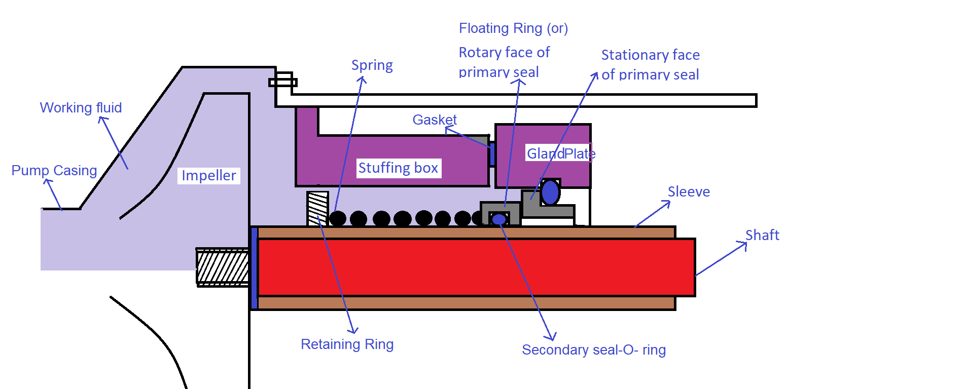
A typical mechanical seal consists of the following components. They are
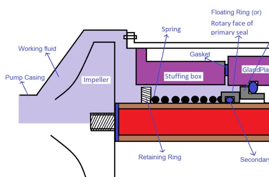
- Floating ring (or) Rotary part of a primary seal
- Stationary ring (or) Stationary part of a primary seal
- Secondary seal or O-ring
- Spring/bellow
- Thrust (or) Spring retaining ring
- Gland Plate
A typical centrifugal pump with a mechanical seal is shown in the following figure.
5 Different Seal Points of a Mechanical Seal
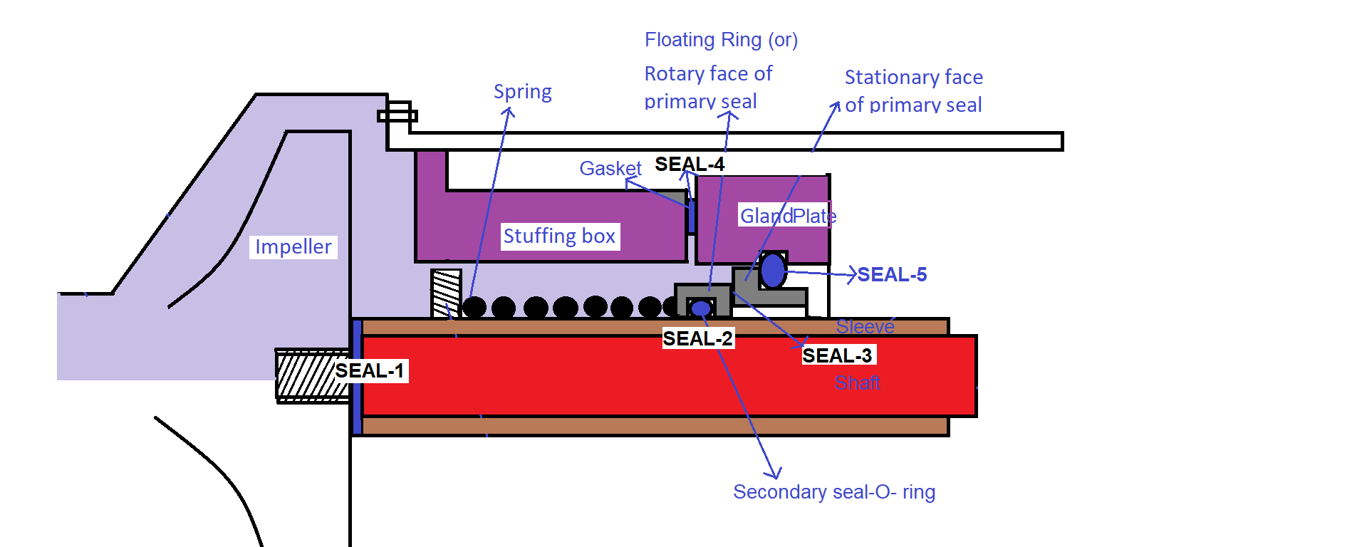
A typical mechanical seal has 5 different seal points to prevent pressurized fluid from leaking into the surroundings.
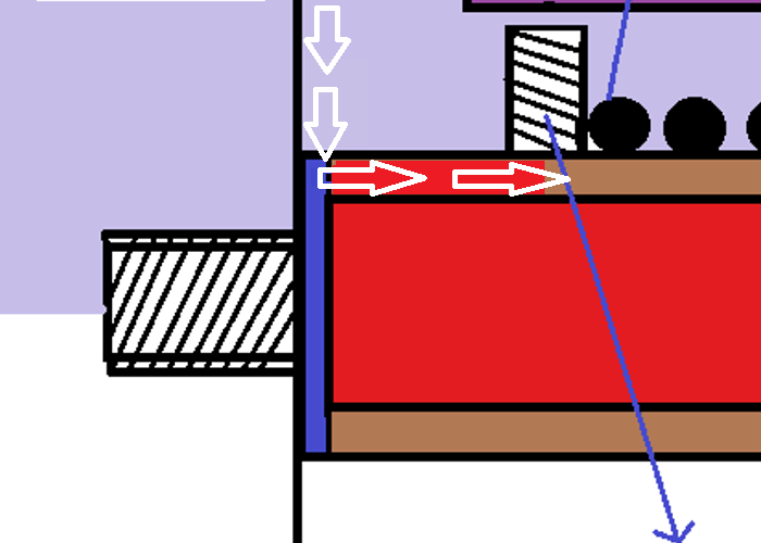
Seal Point-1: Seal Between the Sleeve and the Shaft
The seal is located between the impeller and shaft & sleeve as shown in the figure-2 i.e., gasket. It prevents fluid leakage through the gap between the shaft and sleeve as shown in the following figure. The seal is rotary (impeller) against rotary part (shaft & sleeve) seal. But there is no relative movement between the parts during operation. The arrows in the following figure indicate a possible leak if the seal is not available.
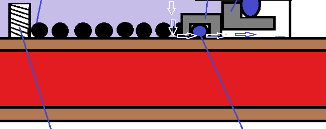
Seal Point-2: Secondary Seal or O-Ring
The seal is located between the floating ring and the shaft sleeve as shown in the figure-2 i.e., O-ring. It prevents the fluid leak through the gap between the floating ring (rotary part of primary seal) and the shaft sleeve as shown in the following figure. The seal is rotary against the rotary part seal. During the operation, the sleeve and O-ring move relative to one another. The arrows in the following figure indicate a possible leak if the seal is not available.
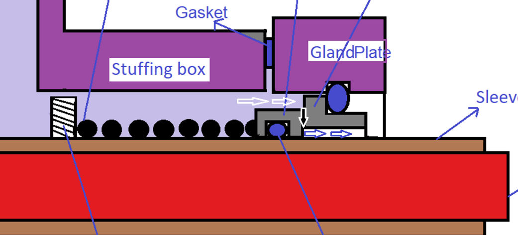
Seal Point-3: Primary Seal
The rotary and stationary portions are sealed by the floating ring rotating against the stationary ring (rubbing against each other). The floating ring is intact with a stationary ring due to spring force (spring has a predetermined compression of 2 to 3 mm) and hydraulic load (due to fluid pressure acting on the sealing surface). The seal is rotary against a stationary part seal. The arrows in the following figure indicate a possible leak if the seal is not available.
What is the role of spring in the mechanical seal?
- Automatically compensates for seal face wear by enabling the floating ring to move axially.
- Accommodates misalignment of seal faces.
- Accommodate thermal expansion of seal rings in an axial direction. The heat generated by contact between the faces may cause the seal ring to expand thermally.
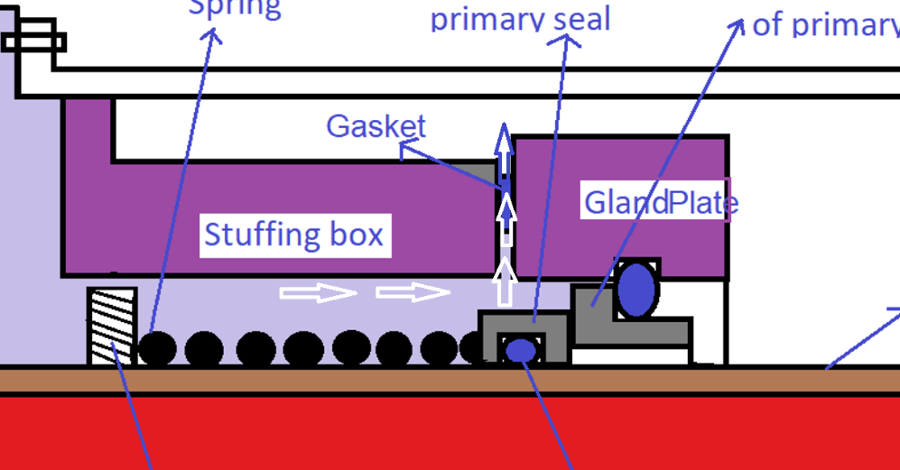
Seal Point-4: Seal Between the Stuffing Box and the Gland Plate
The seal is located between the stuffing box and the gland plate i.e., the gasket. It is stationary against the stationary part seal. The arrows in the following figure indicate a possible leak if the seal is not available.
Seal Point-5: Seal Between the Stationary Ring and the Gland Plate
The seal is located between the stationary ring and the gland plate. It is stationary against the stationary part seal. The arrows in the following figure indicate a possible leak if the seal is not available.
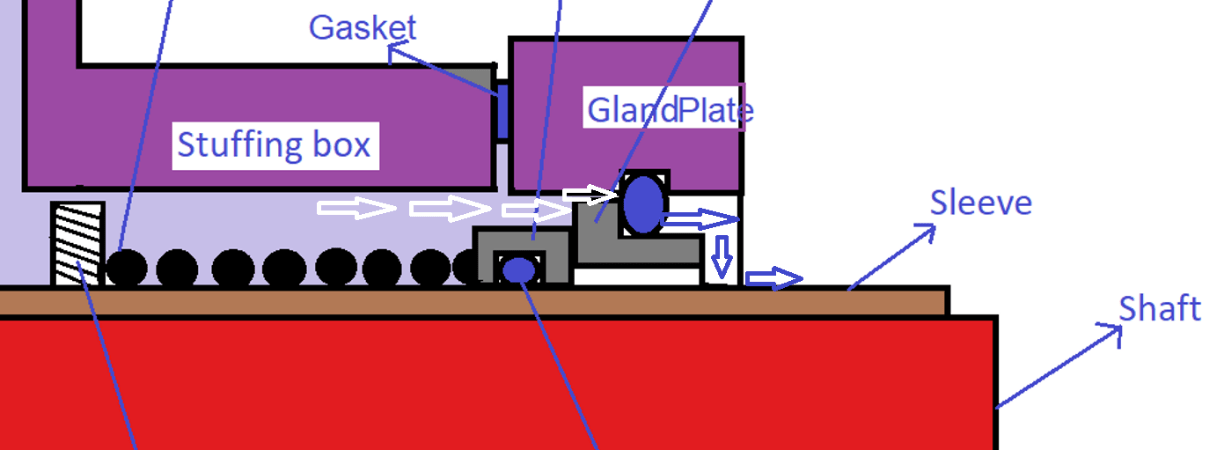
FAQ on Mechanical Seal
1. Why mechanical seal is called “mechanical”?
Because the primary sealing i.e., Contact between the rotary seal ring and stationary seal ring is aided by a mechanical spring or a bellow.
2. Who was the inventor of the mechanical seal?
In the year 1923, George J. Cooke designed the first mechanical seal for refrigeration compressors.
Courtesy: End-face mechanical seal – Wikipedia
3. What is the formula for calculating the rubbing velocity of seal faces?
The following equation can be used to compute the rubbing velocity of a rotating seal against a stationary seal face.
![]()
Where V represents the sliding or rubbing velocity of the seal face. Unit in m/s
D represents the mean diameter of the rotating seal face. Unit in m
N represents the rotation speed of the shaft. Unit in rotations/s
