Table of Contents
Double Mechanical Seal
A double mechanical seal contains two primary seals whereas a single mechanical seal has only one primary seal. Out of two primary seals, one seal is with the process fluid side and the other is with the atmospheric side. The atmospheric side seal acts as a backup.
Generally, there is no liquid leakage from a single mechanical seal. But there can be a leakage in the form of vapour due to the vaporization of liquid which is being used for removing the generated heat because of friction between two rubbing mating rings and the shear of hydrodynamic film between two mating rings.
If the pumping fluid itself is used for cooling and lubricating the seal, then there can be environmental pollution due to the vaporization of the process fluid. Instead of self-cooling, if API Plan-32 is preferred i.e., cooling the seal by using the external water, there can be a problem of product dilution. Under stringent environmental regulations and product quality conditions, a dual mechanical seal is preferred instead of a single mechanical seal.
Standards followed for mechanical seal: ISO 21049
Different Types of Double Mechanical Seals
A double mechanical seal can have 3 possible arrangements based on the relative axial orientation of each seal mounted on the shaft as per ISO-21049. They are
- Face to Back (FB)
- Back-to-Back (BB)
- Face to Face (FF)
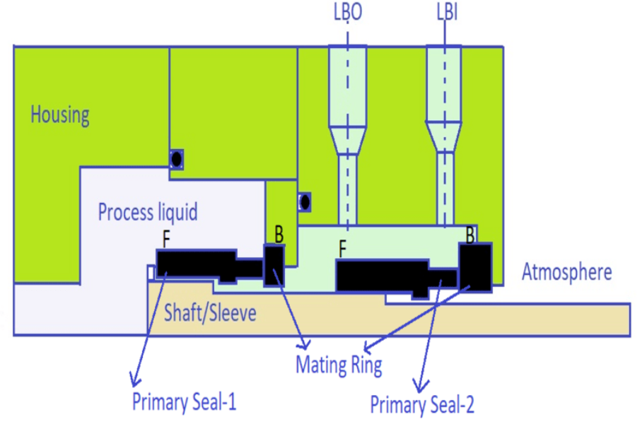
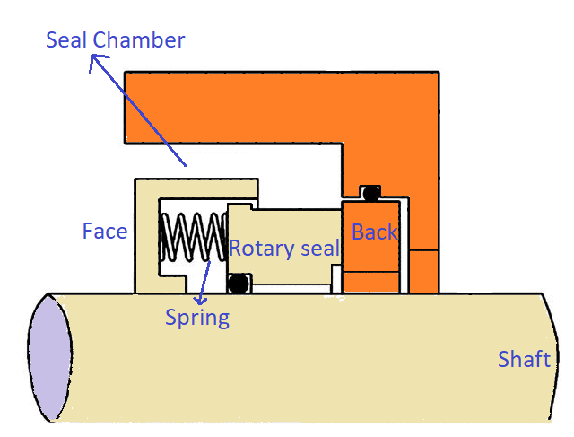
The face and back of a typical mechanical seal are shown in the below figure.
1. Face-to-Back Mechanical Seal Configuration

The location of the flexible element (spring/bellow) is called the face and the location of the mating ring of the seal is called back.
Arrangement: F B F B
- One mating ring is located between two flexible elements and one flexible element is located between two mating rings.
- Both seal faces are in the same direction.
- The upper portion of the rotary part of primary seal-1 is in contact with the process liquid.
2. Back-to-Back Mechanical Seal Configuration
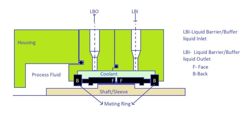
Arrangement: B F F B
- Both flexible elements are located between two mating rings.
- The lower portion of the rotary and mating ring of primary seal-1 is in contact with the process liquid.
3. Face-to-Face Mechanical Seal Configuration
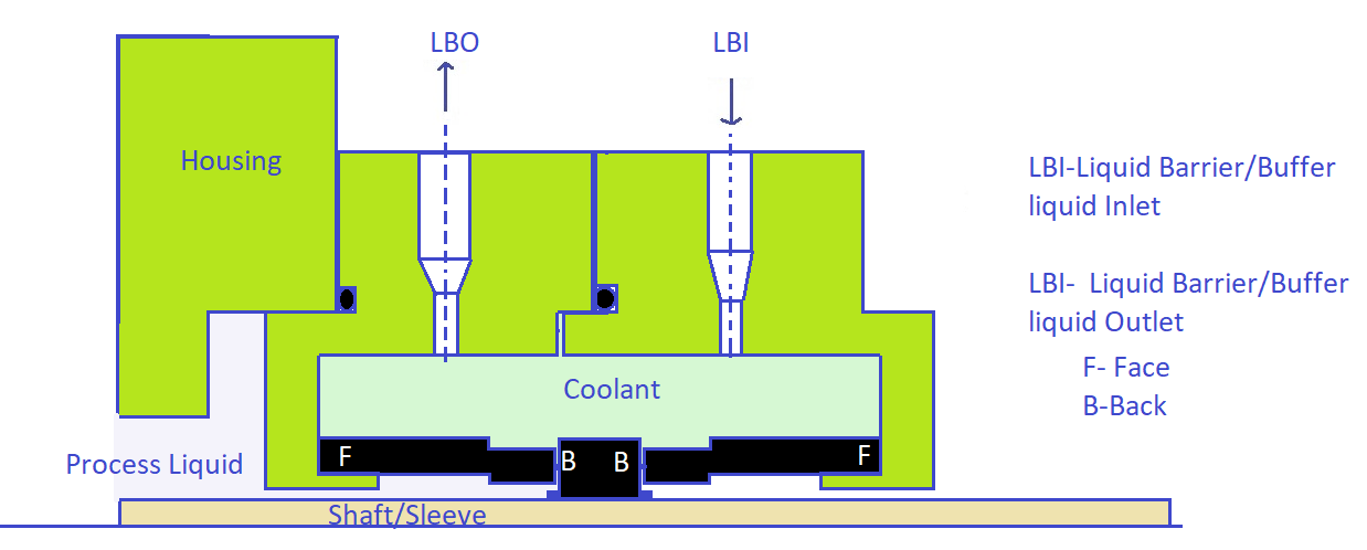
Arrangement: F B B F
- Both the mating rings are located between the flexible elements.
- The flexible element is mounted to the stationary part i.e., gland follower and the mating ring is mounted to the rotary part i.e., shaft/sleeve.
A double mechanical seal has two different configurations based on the type of external cooling arrangements. They are
- Un Pressurised Double Mechanical Seal
- Pressurised Double Mechanical Seal
1. Unpressurised Double Mechanical Seal
An unpressurised double mechanical seal arrangement is called “Arrangement -2” as per ISO-21049. (“Arrangement-1” refers to a single mechanical seal).
Consider a typical face-to-back seal arrangement as shown in the figure below.
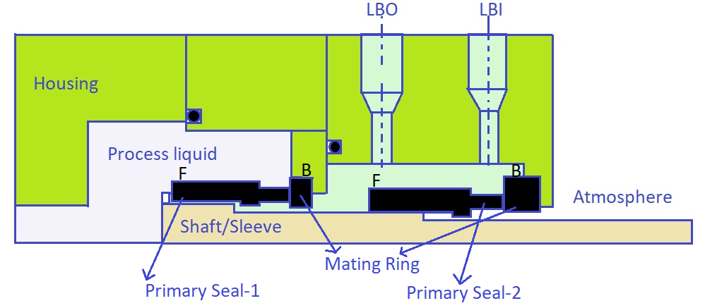
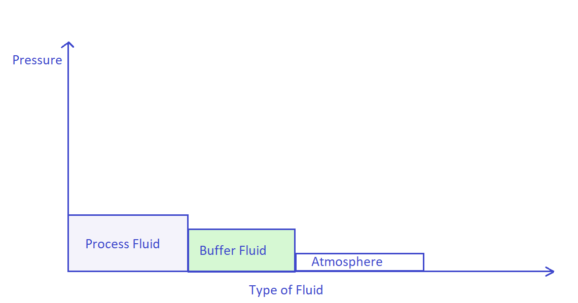
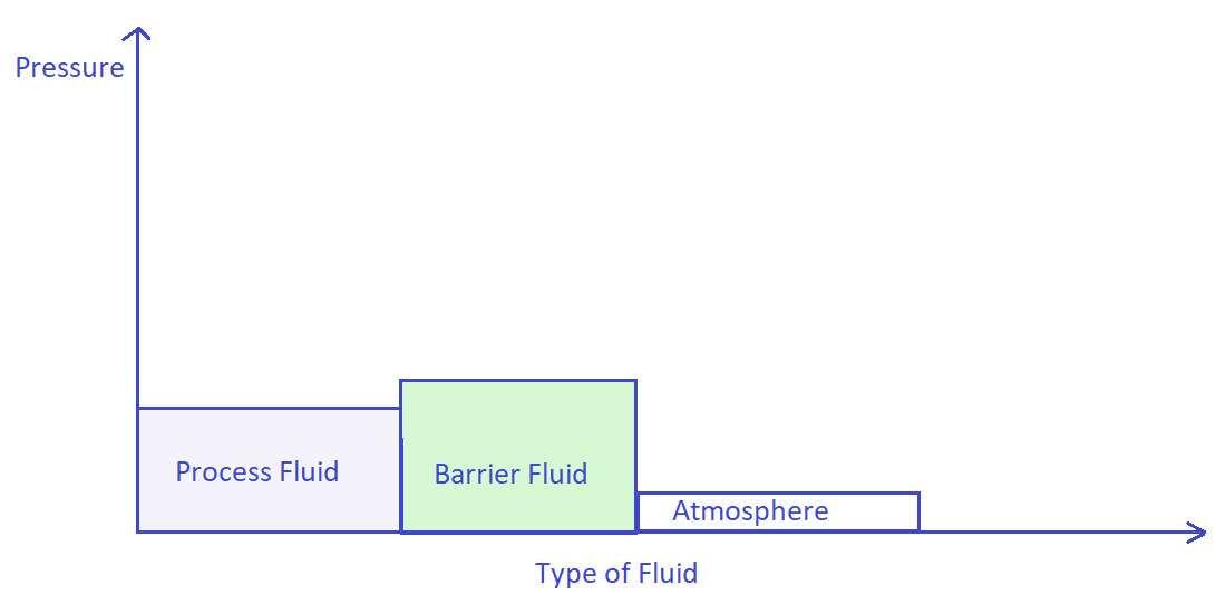
Buffer fluid represents the seal cooling liquid having pressure lower than pumped fluid but higher than atmospheric pressure as shown in figure-5.
Failure of the process side seal causes the leakage of process liquid into buffer liquid and contaminates it. If the process fluid is slurry, the failure of the process side seal leads to failure of the atmospheric side seal due to the deposition of slurry in the face portion i.e., between the coils of spring/bellow. In this case, the spring loses its compression or expansion action leading to premature failure of the mechanical seal.
Advantage: No dilution of process side fluid even in case of primary seal-1 failure.
Application of Unpressurised Double Mechanical Seal
An unpressurised dual mechanical seal is used where the product quality is of utmost importance like food and beverages industries.
2. Pressurised Double Mechanical Seal
Pressurised double mechanical seal arrangement is called “Arrangement-3” as per ISO-21049.
Barrier fluid of pressure higher than process fluid is used to cool and lubricate the seal faces. In general, the pressure of barrier fluid is 1.75 bars higher than process fluid.
Advantage: Even in case of primary seal-1 failure, the process fluid will not pollute the environment.
Application of Pressurised Double Mechanical Seal
A pressurised double mechanical seal is preferred where the process fluid is hazardous in nature like radioactive wastes and harmful chemicals. Etc.
The following table represents the advantages and disadvantages of double mechanical seals of different possible configurations.
| Face to Back | Back-to-Back | Face to Face | |
| Un-Pressurised | 1. The stationary portion of the process side seal is in contact with the process fluid. 2. Possible contamination of seal cooling fluid. 3. Failure of the process side seal leads to failure of atmospheric side seal. 4. Process fluid leak into the atmosphere is inevitable if both seals fail. | 1. The stationary portion of the process side seal is in contact with the process fluid. 2. Possible contamination of seal cooling fluid. 3. Failure of the process side seal leads to failure of the atmospheric side seal. 4. Process fluid leak into the atmosphere is inevitable if both seals fail. | Same as the Face to Back configuration. |
| Pressurised | 1. Spring/bellow is in contact with the process fluid. 2. No possible contamination of seal cooling fluid. 3. Possible dilution of the process fluid. 4. Process fluid can never leak into the atmosphere even in the case of seal failure. | 1. The stationary portion of the process side seal is in contact with the process fluid. 2. No possible contamination of seal cooling fluid. 3. Possible dilution of the process fluid. 4. Process fluid can never leak into the atmosphere even in the case of seal failure. | Same as the Face to Back configuration. |
FAQs on Double Mechanical Seal
1. Why double mechanical seal is used?
Why double mechanical seal is used? – The Mechanical Engineer (amechieneer.com)
