Table of Contents
Balancing of Rigid Rotating Systems
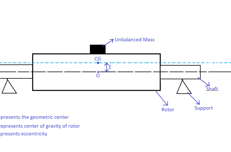
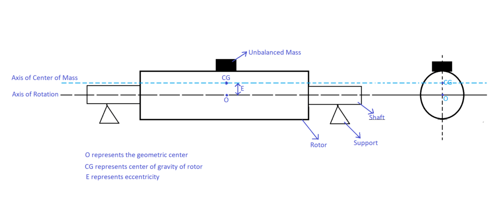
The purpose of balancing is to balance the centrifugal forces and moments that are induced due to the non-uniform distribution of mass around the axis of rotation (or shaft axis) by adding or removing the material from the rotor. The axis of rotation does not coincide with the mass center (center of gravity CG) of a rotor in an unbalanced system as shown in the following figure. Generally, a shaft is mounted to the rotor at the geometric center. If the mass is distributed evenly, the geometric center of the rotor coincides with the axis of rotation otherwise there will be a gap between them (called eccentricity) as shown in the following figure. Because of the unbalanced mass (mu), CG shifted from O by eccentricity E.
This article is about the balancing of rigid rotating systems. A rotor is said to be rigid if its operating speed is less than 70 % of its first critical speed. At critical speed, the rotor along with the shaft deflects with high amplitude that leads to the displacement of its adjacent material (nothing but shaft deforms significantly) thus, it can no longer be called a rigid system.
Difference Between Imbalance and unbalance
Imbalance is a noun. A noun just refers to a thing without indicating the action.
Unbalance is a verb. A verb refers to some action, experience, condition. It means unbalance i.e., the verb form indicates to cause the loss of balance.
Effects of Unbalance in Rotating Machinery
Rotor always tries to rotate about its center of mass but the bearings (on which the rotor is supported) restrict the lateral movement of the unbalanced rotor. This leads to the generation of vibration and reduces the bearing life.
Causes of Unbalance in Rotating Machinery
Casting error- Formation of blowholes during casting
Blowholes are the tiny empty spaces in the casted metal due to the presence of gas bubbles inside the molten metal during solidification because of the lack of sufficient porosity in the mould.
Operational Environment- Dirt build-up
In general, centrifugal fans handling dirty air (i.e., air containing solid particles), dirt or dust tries to build upon the blades of the impeller that leads to uneven distribution of mass around the axis of rotation.
Assembling Error
While making a hole on the rotor to insert the shaft, the hole may not be exactly concentric with respect to the rotor.
Types of Unbalance in Rigid Rotating Systems
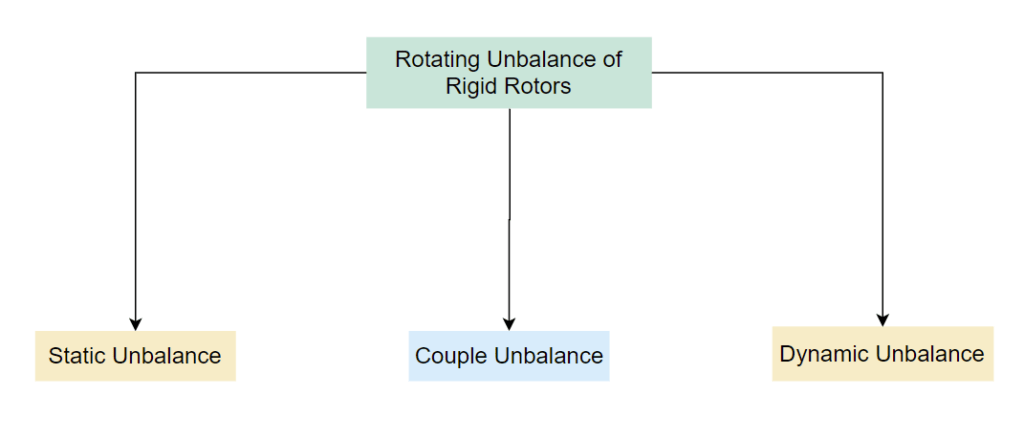
Unbalance in rigid rotating systems is classified into three types based on the relative position of the axis of rotation (i.e., shaft axis) and axis of center of mass (i.e., center of gravity) of rotating rigid rotor. They are
Static Unbalance or Force Unbalance
The Axis of centre of mass is displaced parallel to the shaft axis due to the non-uniform distribution of mass around the axis of rotation as shown in the following figure.
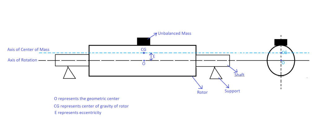
This is called static unbalance because it can be seen visually even the rotor is in a stationary condition. An unbalanced mass (mu) on the above shown single rotor system can be treated as an example of static unbalance. When this type of rotor is rotated by hand or by a machine, it always tries to stop at 6’O clock position due to gravity.
Balancing the Static Unbalance
Figure 3 can be replaced with the following equivalent figure.
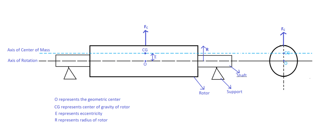
“Centri” means centre and “fuge” means away so, centrifugal force always acts away from the centre towards outward direction. Unbalanced mass (mu) can be replaced with centrifugal force (Fu) (as shown in the above figure) of magnitude muR![]() where R is the radial location of the unbalanced mass,
where R is the radial location of the unbalanced mass, ![]() is the angular velocity of the rotor. Since the line of action of centrifugal force is coinciding with the geometric centre O, no moments or couples will be induced.
is the angular velocity of the rotor. Since the line of action of centrifugal force is coinciding with the geometric centre O, no moments or couples will be induced.
Static unbalance can be balanced by balancing the centrifugal force alone. The above rotor can be balanced by adding the counter mass (mc) of equal weight as of unbalanced mass (mu) at an equal radius from the axis of rotation at ![]() in the same plane perpendicular to the axis of rotation that contains the unbalanced mass (dark blue colour represents the counter mass (mc)) as shown in the figure below. Thus,
in the same plane perpendicular to the axis of rotation that contains the unbalanced mass (dark blue colour represents the counter mass (mc)) as shown in the figure below. Thus, ![]() .
.
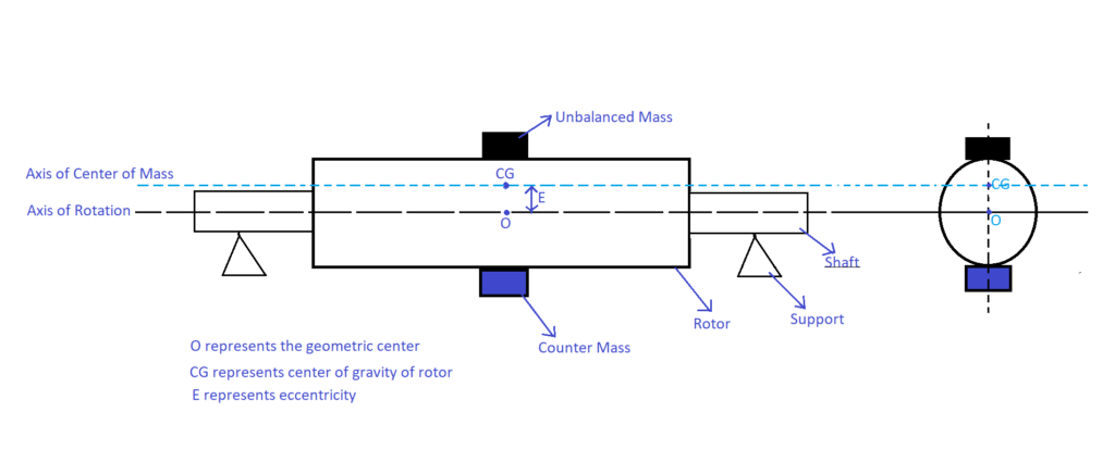
Or else it can be balanced by removing the unbalanced mass mu from the rotor.
Couple Unbalance
The axis of mass is inclined and intersects the axis of rotation at the centre of gravity as shown in the following figure. Eccentricity is zero since both CG and O coincides.
Note: Pure couple is an ideal case. The probability of occurrence of pure couple unbalance is very rare.
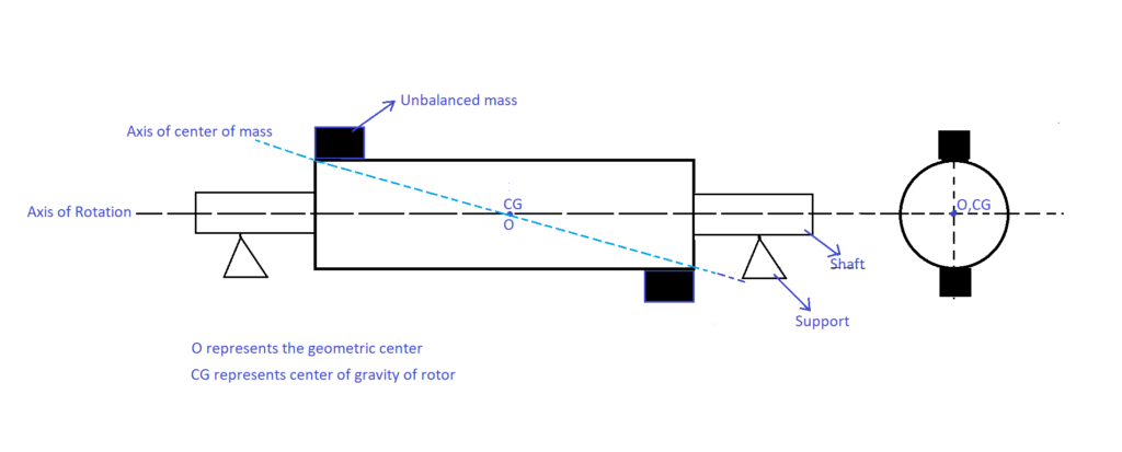
Figure 6 can be replaced with the following equivalent figure.
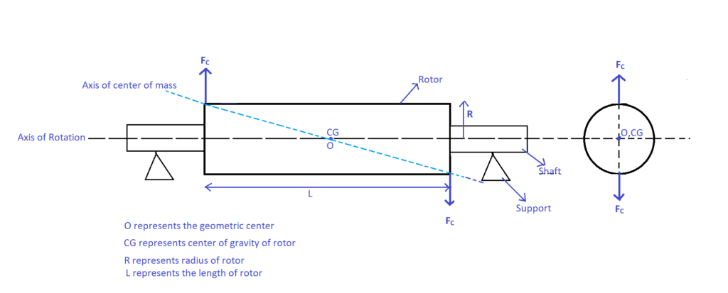
Even though the centrifugal forces are balanced by themselves i.e., ![]() but the line of action of these forces are not coinciding with the geometric centre thus, a moment or a couple will be induced. Since the equal amount of unbalanced mass is located at
but the line of action of these forces are not coinciding with the geometric centre thus, a moment or a couple will be induced. Since the equal amount of unbalanced mass is located at ![]() to each other, a couple of magnitude Fu
to each other, a couple of magnitude Fu ![]() will be induced.
will be induced.
Balancing the Couple Unbalance
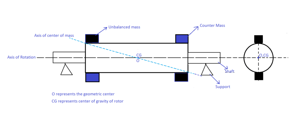
Centrifugal forces are balanced, only a couple needs to be balanced. It can be balanced by adding the counter mass of equal weight as of unbalanced mass at the same radius at the same plane that contains the unbalanced mass at ![]() . Hence, counter mass (blue colour in the following figure) has to be added in two planes perpendicular to the axis of rotation as shown in the following figure.
. Hence, counter mass (blue colour in the following figure) has to be added in two planes perpendicular to the axis of rotation as shown in the following figure.
Dynamic Unbalance
The axis of mass is neither parallel nor intersecting the axis of rotation at the geometric centre O as shown in the following figure. The eccentricity is at an offset to the geometric centre O. Dynamic unbalance is the combination of both force and moment unbalance.
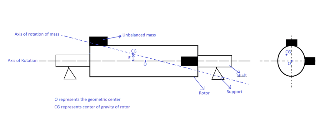
The above figure is equivalent to the following figure.
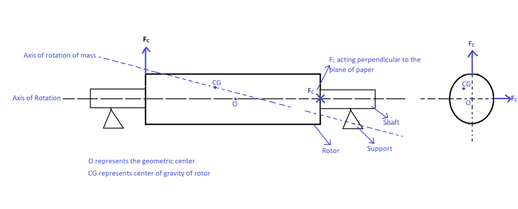
Balancing the Dynamic Unbalance
Centrifugal forces and moments are not balanced i.e., ![]()
![]() . Minimum two planes are needed to balance the dynamic unbalance. Any added counter mass should satisfy the above mentioned condition for a rotor to get balanced completely.
. Minimum two planes are needed to balance the dynamic unbalance. Any added counter mass should satisfy the above mentioned condition for a rotor to get balanced completely.
