Table of Contents
In the world of industrial steam systems, there’s an essential component known as the thermodynamic steam trap. Its primary function is to maintain the integrity of the steam, ensuring that it’s free from any unwanted condensate and non-condensable gases. This seemingly simple device plays a crucial role in preventing catastrophic damage to equipment and maintaining the efficiency of steam-driven processes. In this article, we’ll delve into the purpose, construction, working principles, advantages, drawbacks, and troubleshooting aspects of thermodynamic steam traps.
Purpose of Steam Traps Installation
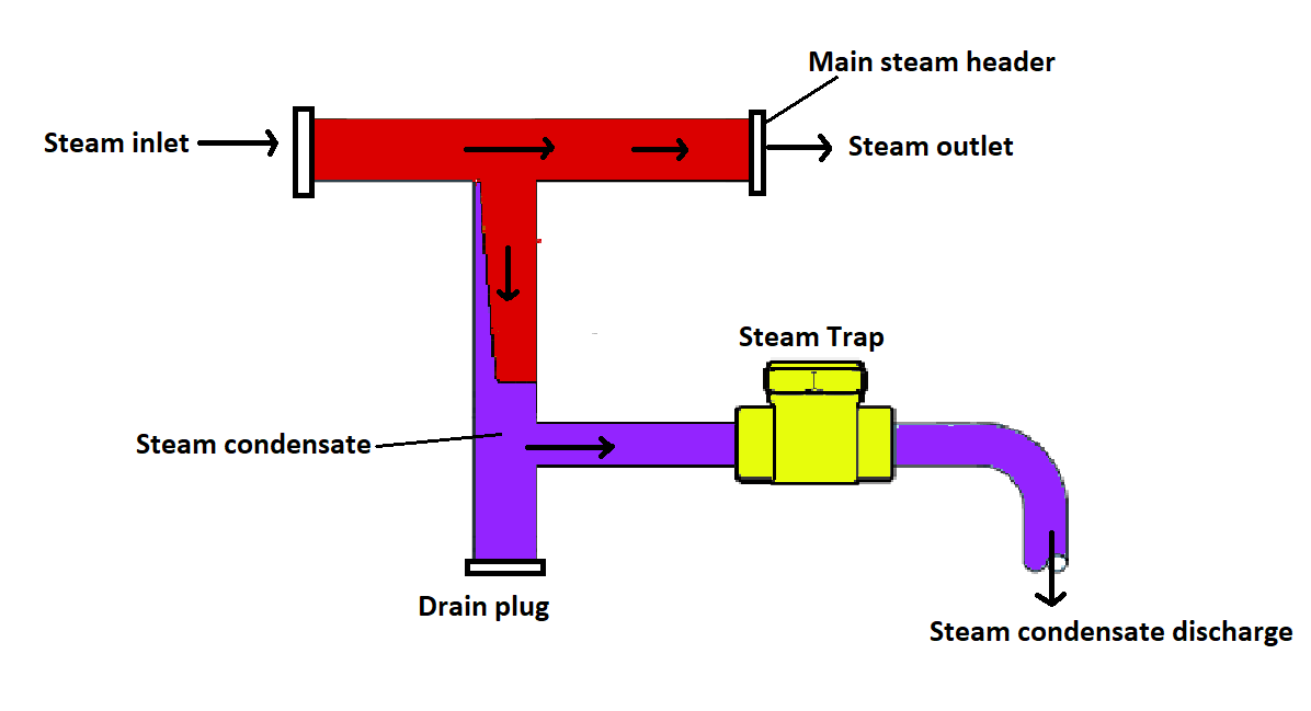
Steam, originating from sources like boilers, undergoes a journey from its point of creation to its ultimate destination in various industrial equipment. However, during this journey, a portion of the steam condenses due to pressure drops in the pipeline. This condensed water, referred to as condensate, must be efficiently removed. If not, the high-velocity steam can carry this condensate, leading to disastrous consequences. When condensate moving with high velocity collides with downstream bends or equipment, it generates a high-pressure shockwave, resulting in severe damage.
The primary objective of a steam trap is to selectively retain steam while discharging condensate. This prevents the escape of valuable steam while maintaining the integrity of the steam system.
Flash Steam: The Unusual Sibling of Normal Steam
Steam typically originates from processes like boiler operation, steam generation, and the like, making it known as “normal” or “live” steam. However, flash steam, while similar in many respects, differs in its source of production. It is born when hot, high-pressure condensate undergoes a substantial pressure drop. This phenomenon can be vividly explained using a T-S graph.
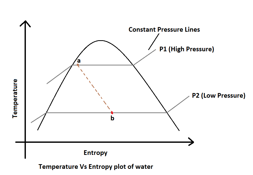
Point ‘a’ on this graph represents steam condensate at high pressure (![]() ). Due to the inherently irreversible nature of this process, entropy increases, leading to point ‘b’ at lower pressure (
). Due to the inherently irreversible nature of this process, entropy increases, leading to point ‘b’ at lower pressure (![]() ). At this stage, the fluid at point ‘b’ contains roughly 55% vapor in steam form and 45% liquid in condensate form.
). At this stage, the fluid at point ‘b’ contains roughly 55% vapor in steam form and 45% liquid in condensate form.
Thermodynamic Steam Trap Components
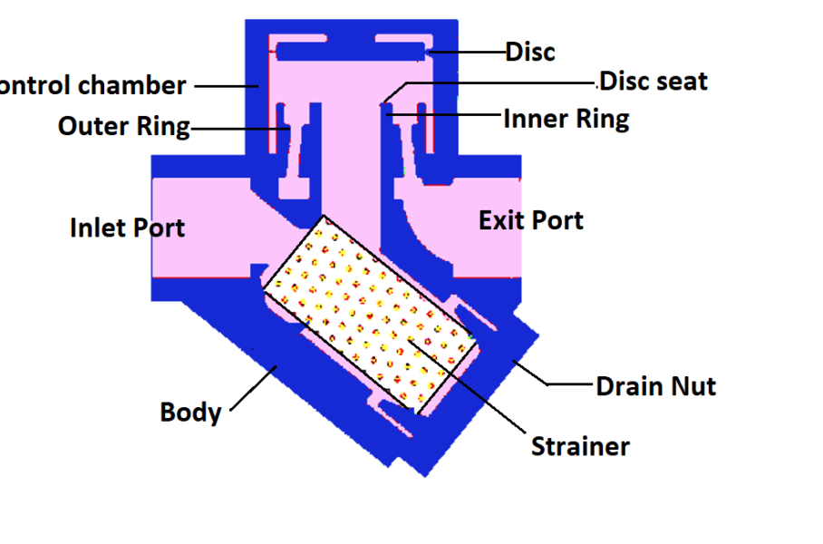
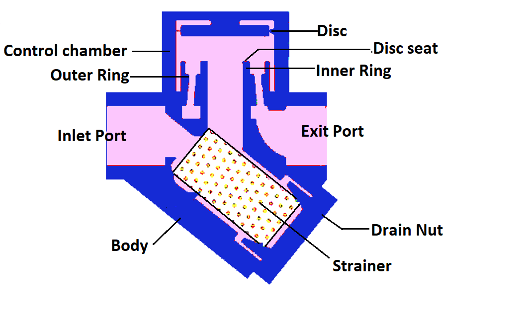
A thermodynamic steam trap comprises several key components as shown in the figure below.
- Inlet port
- Strainer
- Inner ring
- Outer ring
- Disc
- Control chamber
- Outlet port
- Disc seat
- Body
- Drain nut
Construction of Thermodynamic Steam Trap
The presence of both inner and outer rings serves to prevent short-circuiting between the inlet and outlet steam, enhancing the trap’s efficiency. The surface area on the top of the disc is more than its bottom side. For the same pressure, the force on the top of the disc is more than the force on the bottom of the disc. Hence the closing force is greater than the opening force.
How a Thermodynamic Steam Trap Works?
The working principle of a thermodynamic steam trap is rooted in the Bernoulli principle, which states that an increase in fluid velocity corresponds to a decrease in fluid pressure. In the context of steam traps, this principle is employed to discharge condensate while trapping steam from escaping.
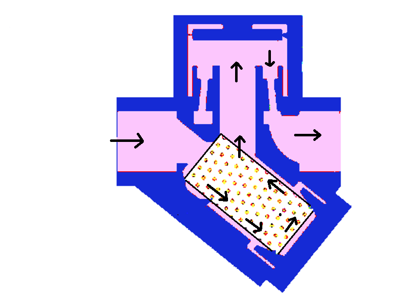
As the fluid flowing through the trap is a mixture of liquid and gas, the distinct thermodynamic properties of liquid and gaseous states are utilized to facilitate condensate removal. The steam flowing path in the thermodynamic trap is shown in the figure below.
Startup (Step-1)
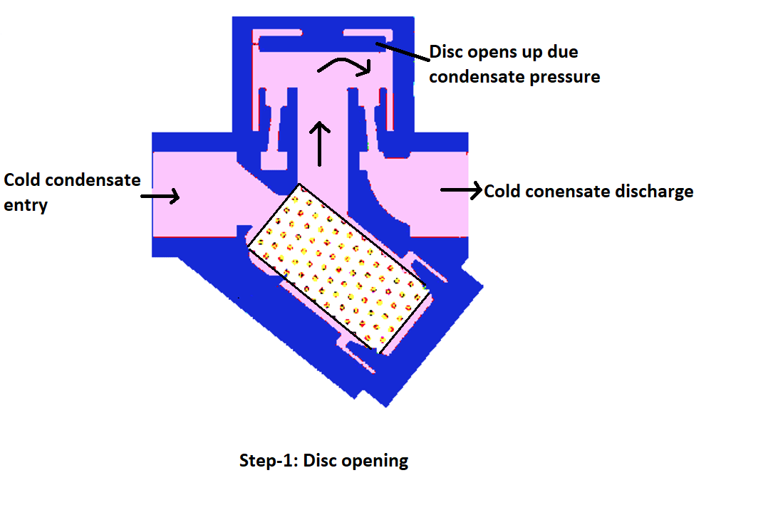
During startup, relatively cold condensate passes through the steam trap, opening the disc and allowing condensate to be discharged.
Closing of Disc (Step-2)
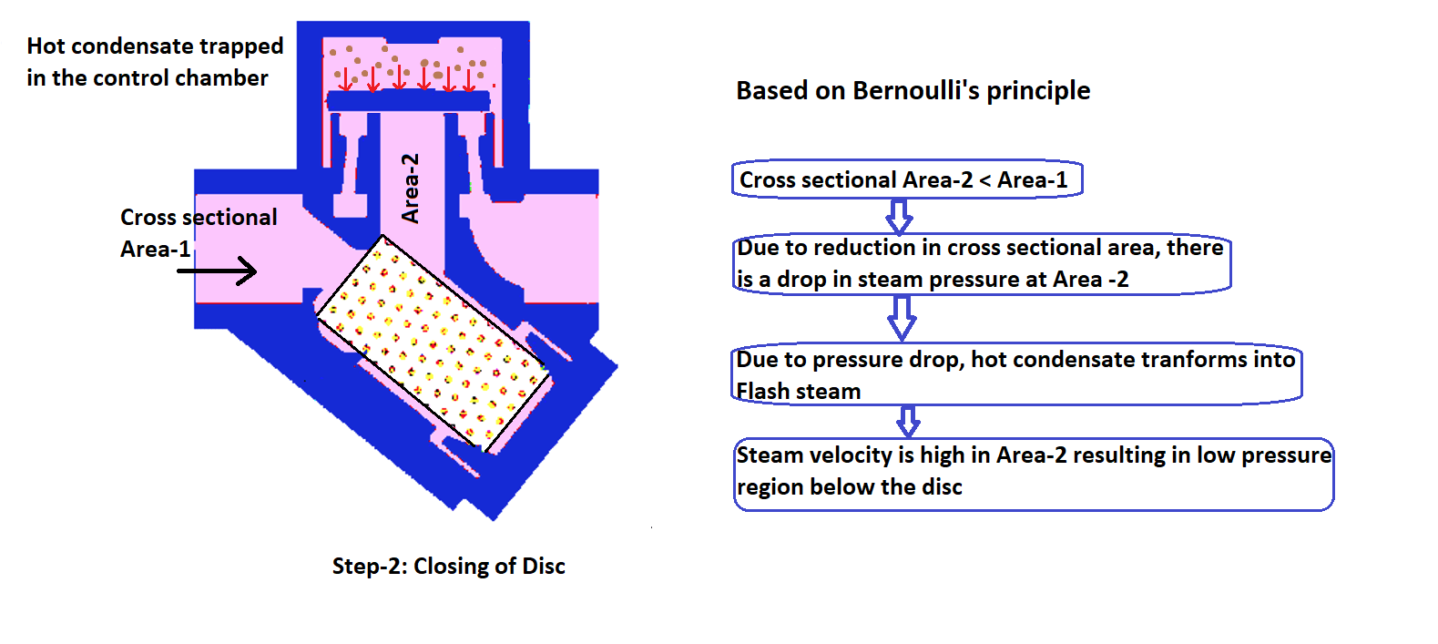
As hot condensate at the downstream side experiences a pressure drop at the disc’s inlet because of reduced cross-section, it transforms into flash steam. Due to the higher velocity of the steam compared to the condensate, a low-pressure region is created beneath the disc. This leads to the disc falling onto its seat. The closing of the disc is further aided by the flash steam trapped in the control chamber. The disc is designed with a larger surface area at the top side, ensuring it seats correctly.
Opening of Disc (Step-3)
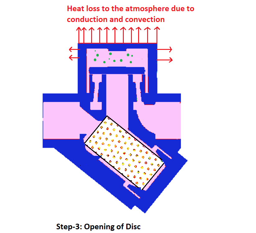
The flash steam, trapped in the control chamber, gradually loses temperature due to heat loss via conduction and convection as shown in the above figure. As a result, the closing force on the disc reduces. Simultaneously, incoming steam condensate, with a relatively higher pressure, lifts the disc, and the cycle repeats.
Drawbacks of Thermodynamic Steam Traps
While thermodynamic steam traps offer several advantages, they also have some limitations:
- Minimum Inlet Pressure Requirement: These traps require a minimum threshold inlet pressure of 0.25 kg/cm² (g) for the disc to open. This is possible at high steam velocities which demand a minimum threshold inlet pressure of 0.25 kg/cm² (g).
- Live Steam Loss: Approximately 14.5 grams of live steam is discharged in each cycle of operation.
- Air Binding: When air becomes trapped in the control chamber above the disc, it prevents quick condensation and, consequently, delays the reduction of pressure on the disc, leading to longer cycle times.
Thermodynamic Steam Trap Benefits in Industry
Despite the drawbacks, thermodynamic steam traps have notable advantages:
- Simplicity and Low Maintenance: The disc is the only moving part in these traps, which translates to minimal maintenance requirements.
- Compact Design: They are compact in size and require minimal space in piping systems.
Steam Trap Troubleshooting Tips
If issues arise with thermodynamic steam traps, here are some common troubleshooting steps:
1. Continuous Steam Discharge:
This may be due to the accumulation of dirt beneath the disc or the disc getting stuck in the control chamber during a cycle.
2. Rapid Cycling (Machine Gunning):
This occurs when the steam trapped in the control chamber loses heat too quickly, leading to frequent disc opening and closing. Insulating the control chamber’s outer body can mitigate this issue.
3. No Discharge:
If the disc doesn’t open, it could be due to the presence of non-condensable gases on the disc in the control chamber.
Interesting Facts About Thermodynamic Steam Traps
A couple of noteworthy facts about thermodynamic steam traps:
- The disc in a thermodynamic steam trap opens once every 30 to 60 seconds, emphasizing their cyclical operation.
- The valve seat of thermodynamic steam traps typically has a martensitic crystal structure, known for its high hardness. This reduces wear and tear on the seat due to the frequent opening and closing of the disc.
Thermodynamic Steam Trap Frequently Asked Questions (FAQ)
Q1: Can thermodynamic steam traps be installed vertically?
Yes, thermodynamic steam traps can indeed be installed vertically. The opening and closing of the disc depend on the pressure difference between the top and bottom sides of the disc, rather than factors like buoyancy or gravity of the disc. This flexibility makes them suitable for vertical installations.
In conclusion, thermodynamic steam traps are unsung heroes in industrial steam systems, diligently ensuring the efficient flow of steam while preventing condensate-related disasters. Understanding their purpose, construction, working principles, and troubleshooting methods can help industries make the most of these unassuming yet vital components.
