Table of Contents
Introduction
As we discussed in previous articles, the mechanical vibration of running equipment is a language through which a machine communicates its faults to the machine operator. Following are some of the machinery faults detectable by the vibration analysis.
- Misalignment between driver and driven machines, i.e., axial or radial misalignment
- Unbalance, i.e., static, dynamic, or couple unbalance in rotating parts
- Structural looseness, i.e., loose foundations
- Bent shaft and its location of the bend
- Bearing failure and its location, i.e., on the ball or inner race or outer race or cage
- Gear tooth wear
- Eccentric rotor, i.e., offset between shaft and impeller
- Cocked bearing, i.e., improper installation of bearings on the shaft
- Resonance
- Cavitation
There are three major parameters to quantify the magnitude of vibration. The vibration magnitude represents the severity of vibration. Those parameters are
- Displacement
- Velocity
- Acceleration
When to use displacement, velocity, and acceleration?
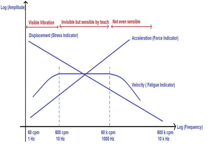
The following graph shows the correct application of parameters with respect to the operating frequency range of machinery.

We will discuss the physics behind the above plot.
Consider a spring-mass system is excited by external harmonic force; obviously, the response of a system is a simple harmonic motion. Then the relation between displacement, velocity, and acceleration of a vibrating system can be represented as follows.
![]()
![]()
![]()
Where D represents displacement of a vibrating body
V represents velocity of a vibrating body
A represents acceleration of a vibrating body
![]() represents the angular frequency
represents the angular frequency ![]()
Now, rewriting the above three equations by considering the maximum amplitudes, we get
![]() …………………. Eq-1
…………………. Eq-1
Displacement
From the equation-1, ![]() . i.e., displacement is inversely proportional to the frequency and the same was shown in figure-1.
. i.e., displacement is inversely proportional to the frequency and the same was shown in figure-1.
At higher frequencies, the displacement of the vibrating body is less. But the question is, “Whether measuring the vibration displacement at high frequencies is worth enough to judge the condition of a rotating machinery?”. The answer is NO.
From Hook’s law of elasticity, induced stress is directly proportional to the strain (i.e., displacement).
![]()
![]()
![]() ……………………………..Eq-2
……………………………..Eq-2
Of course, Hook’s law is valid when the load acting on a component is stationary or the load is a slow variant of time. i.e., if a system is running at low speeds, the induced load (maybe due to rotor imbalance, eccentricity, misalignment. etc.) will vary slowly with respect to time. Hence, the load can be treated almost like a static load.
From eq-2, induced stress in a component is proportional to the displacement. Thus, the induced stress can exceed the design stress limit and eventually fail when displacement is high. Since low frequency corresponds to low rotational speeds of equipment, the vibration displacement is a direct indicator of induced stress within a component. Hence, the magnitude or severity of vibration at low-frequency ranges is represented in displacement.
Note: As a thumb rule, displacement is the preferred vibration parameter when the operating speed of the equipment is up to 60 RPM.
Velocity
Velocity represents the rate of displacement per unit time, i.e., indirectly, the rate of loading per unit time. The X-axis of the following S-N (Stress vs. Number of cycles) curve of steel represents the loading cycles, i.e., rate of loading, and the Y-axis represents the induced stress amplitude in a component. A component can fail early if the loading rate is high (i.e., many loading cycles) though the induced stress is within the limit. In this case, the magnitude of displacement is less, and the operator can easily misle that a vibrating body is safe. A component may not fail due to static stress (just like displacement case), but it can fail due to fatigue.
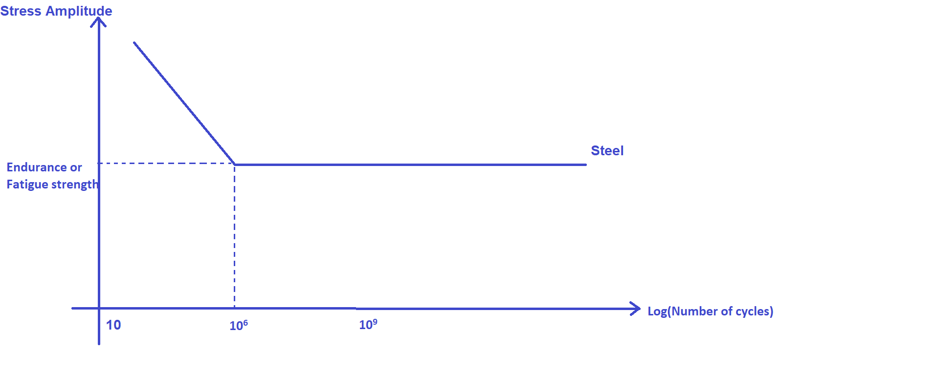
Hence, velocity is a direct indicator of fatigue strength. So, the velocity is preferred to quantify the vibration severity at medium frequency ranges.
Note: As a thumb rule, velocity is the preferred vibration parameter when the operating speed of the equipment is from 60 RPM to 60 K RPM.
Acceleration
From the eq-1, acceleration of a vibrating body is represented as ![]() , and the same is shown in figure-1. Since the acceleration of the vibrating body is proportional to the frequency, acceleration dominates among all the three parameters at a higher frequency. From Newton’s second law of motion
, and the same is shown in figure-1. Since the acceleration of the vibrating body is proportional to the frequency, acceleration dominates among all the three parameters at a higher frequency. From Newton’s second law of motion ![]() , the higher the frequency, the force will be high. Eventually, the force can cause a catastrophic failure.
, the higher the frequency, the force will be high. Eventually, the force can cause a catastrophic failure.
Note: As a thumb rule, acceleration is the preferred vibration parameter when the operating speed of the equipment is above 60 K RPM.
In general, we will not come across any machinery in the industry that runs at 60,000 RPM. Consider a faulty ball bearing with a minor dent in the outer race. The outside race is stationary, while the inner race rotates. When a ball passes over the dent, it causes a high-frequency vibration. Assume that a ball bearing has 30 balls and rotates at 3000 RPM (Standard motor RPM). As a result, each ball that passes over the dent causes vibration. Assume that 25 balls pass over the dent for each rotation of the inner race (due to relative motion between the inner race and the balls, all 30 balls may not pass over the dent in a single rotation of the shaft) and that the bearing induces vibration at a frequency of ![]() cycles per revolution of the inner race. As a result, a vibration with a frequency of 75000 CPM is induced, which cannot be detected by monitoring the displacement or velocity of vibration. Even though the bearing has a minor dent and the net effective mass imposed by the balls on the dent is tiny, the induced force (F=MA) in the bearing is relatively high due to high acceleration, resulting in early bearing failure.
cycles per revolution of the inner race. As a result, a vibration with a frequency of 75000 CPM is induced, which cannot be detected by monitoring the displacement or velocity of vibration. Even though the bearing has a minor dent and the net effective mass imposed by the balls on the dent is tiny, the induced force (F=MA) in the bearing is relatively high due to high acceleration, resulting in early bearing failure.
Note:
A typical industrial vibration meter displays vibration magnitudes in the following units.
Peak to peak displacement in microns (![]() )
)
Root Mean Square (RMS) Velocity in (![]() )
)
Acceleration in (![]() )
)
Why is RMS velocity preferred instead of peak-to-peak velocity?
RMS velocity measured on a vibrating machine represents the energy content of a vibrating waveform. Consider an example, an electric bulb is powered by a DC source of 10 V, and the bulb draws a current of 2 A, as shown in the following figure.
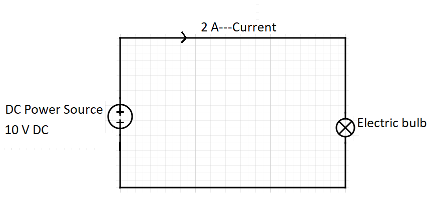
The power consumed by the bulb is 20 W. In the case of DC, the voltage and the current do not change their direction and magnitude with respect to time; hence it is constant and easy to find the magnitude of the power.
Similarly, consider an electric bulb powered by an AC source of 10V (Sinusoidal voltage waveform). Then for every instant, the magnitude and direction of voltage vary with respect to time. Calculation of power consumed by a bulb is complicated in this case. To get an equivalent voltage value in the AC power source like of DC power source, the mean value of voltage is required. The mean value is calculated by squaring the individual voltage values then averaging all the squared individual values and the square root of the averaged value. When the RMS voltage of the AC source is multiplied by the current, it gives exactly the power consumed by the electric bulb. Hence in our case, 10 V RMS AC is equal to 10 V DC. Thus the RMS value is a direct indicator of energy consumed.
Similarly, the vibration velocity of a component under harmonic excitation varies in magnitude and direction; the RMS value is a direct indicator of energy content in the vibration waveform.
