Table of Contents
Refrigerant Screw Compressor
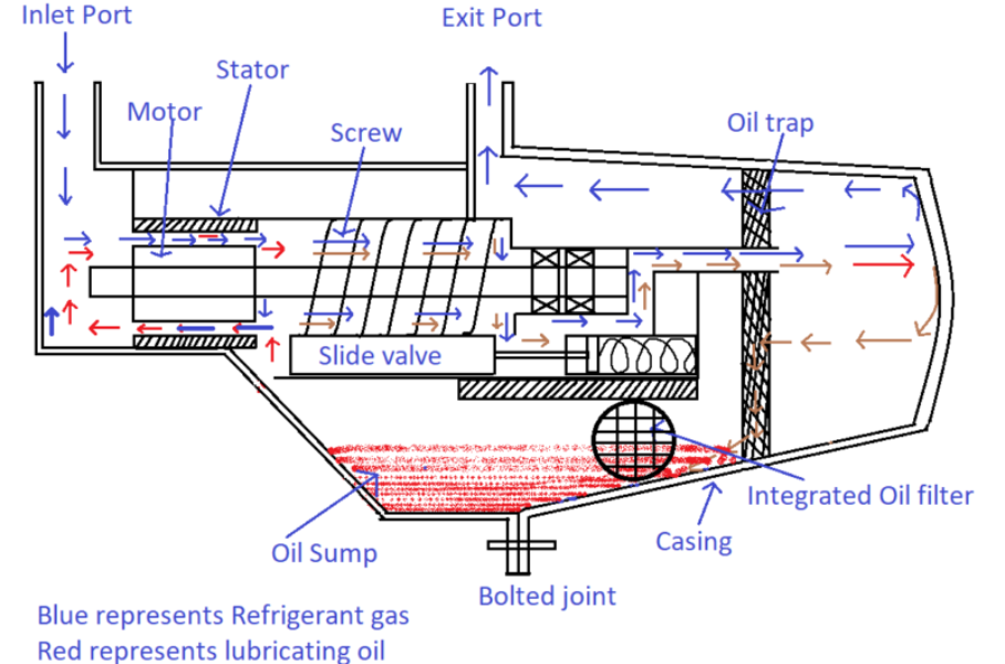
This article focuses on a semi-hermetically sealed twin screw refrigerant compressor. In semi-hermetically sealed compressor, the motor and the compressor are enclosed in a bolted casing. Bolted casing helps in accessing the components inside the casing during a malfunction. But at the same time, the joining surfaces of both halves of the casing must be highly finished and a gasket should be provided to avoid the high-pressure refrigerant leak. A typical refrigerant screw compressor contains the following components as shown in the below figure.
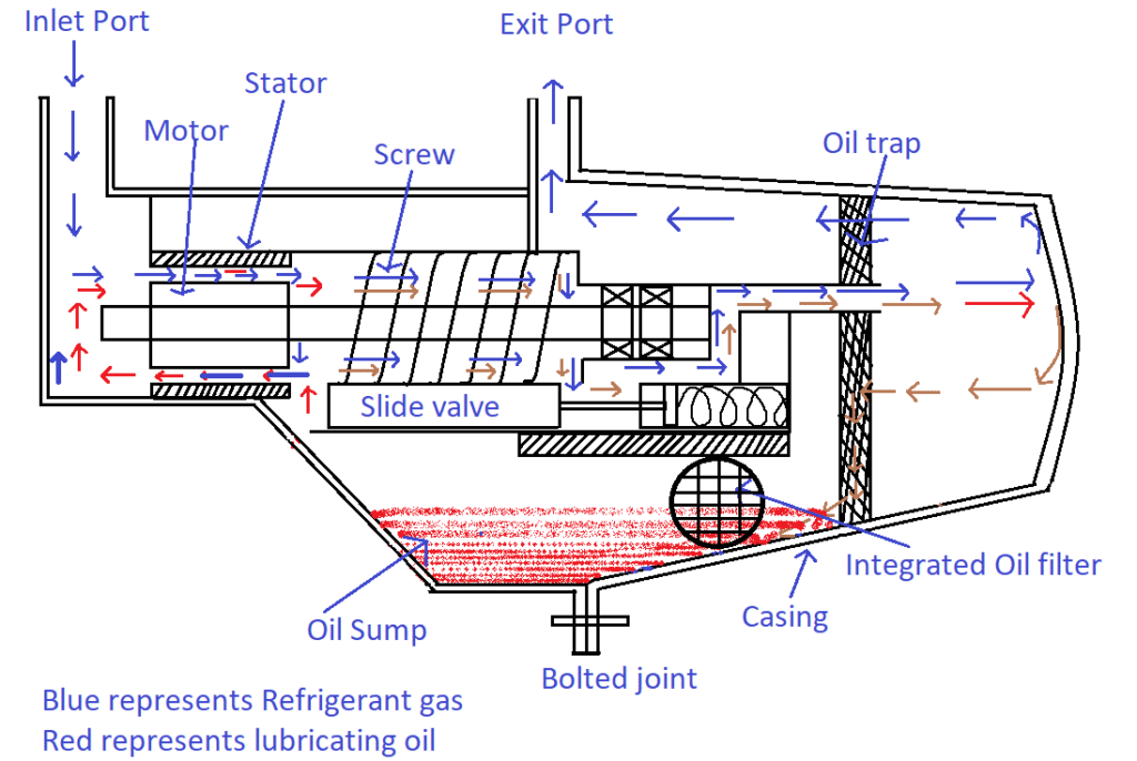
The components are
- Motor
- Twin-screw (Male & Female)
- Sliding Valve or Capacity control valve
- Oil trap
- Compressor Hood
- Oil Sump
- Oil Filter
Working Principle of Refrigerant Twin Screw Compressor
Refrigerant gas leaving the evaporator enters the compressor’s suction port as shown in the above figure (blue color arrows represent refrigerant gas). At the suction zone, the refrigerant gas and the lubricating oil get mixed up and flows through the gap between the stator and the rotor of the motor as shown in the above figure. In general, this type of compressor does not contain an oil pump to circulate the oil within the compressor. Instead, the oil will flow due to the difference in suction and discharge pressure of the refrigerant. Since the compressor is semi-hermetically sealed, instead of a cooling fan, refrigerant gas and oil mixture flowing through the gap cools the motor. Then the mixture reaches the screw and get compressed (How the gas is compressed in a twin-screw compressor? Step by step explanation) and discharged. In general, Polyolester (POE) is used as a lubricant along with R-134a refrigerant gas.
Three Steps of Oil Filtration/Separation from the Refrigerant Gas
Before the refrigerant gas leaves the compressor, the oil should be separated from the gas to avoid the oil carry over to the condenser which can affect the heat transfer efficiency.
Three steps of oil filtration are
- Centrifugal and gravity separation
- Oil trap or demister
- Oil filter
As soon as the mixture discharges from the screws, it hits the compressor hood in its path as shown in the above figure. Due to centrifugal action, denser particles i.e., oil get stick to the hood’s inner surface and flows down towards the oil sump. Since the gas is lighter than the oil, gas moves up and flows through the oil trap. An oil trap or demister is nothing but a steel mesh that creates restriction to the flow. Residual oil in the gas gets trapped in the mesh and flows to the oil sump. 100 % oil separation is not possible, so the tolerance of 10 to 13 ppm of oil is allowed to get carried over by the refrigerant gas.
Capacity Control
Capacity control represents the controlling of cooling capacity of the chiller or any associated refrigeration equipment by controlling the flow of refrigerant through the compressor. Whatever may be the heat load to the evaporator, the compressor should discharge the refrigerant gas at constant discharge pressure even though the refrigerant flow through the compressor is not constant.
Why the discharge pressure of R-134a refrigerant compressor should be maintained at least 6.8 bars?
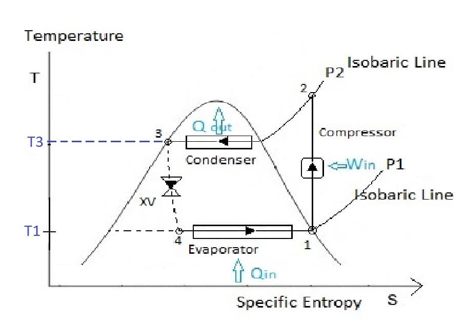
From the above figure, T3 represents the saturation temperature of the refrigerant R-134a corresponding to the compressor discharge pressure P2. In general, P2 of R-134a is in the range of 6.8 to 7.7 bars (absolute). Because the corresponding saturation temperatures for the above-mentioned pressures are 26 to 30 ![]() respectively. The purpose of the condenser is to convert the refrigerant gas into the refrigerant liquid. From the above T-S plot, as the compressor discharge pressure increases, the saturation temperature of R-134a increases. Thus, it is easier to convert the refrigerant gas into a liquid at high discharge pressures. But the limitation is the temperature of condenser cooling water. In general, the raw water at room temperature from the cooling tower is used to cool the condenser. The temperature of raw water will be around 28 to 30
respectively. The purpose of the condenser is to convert the refrigerant gas into the refrigerant liquid. From the above T-S plot, as the compressor discharge pressure increases, the saturation temperature of R-134a increases. Thus, it is easier to convert the refrigerant gas into a liquid at high discharge pressures. But the limitation is the temperature of condenser cooling water. In general, the raw water at room temperature from the cooling tower is used to cool the condenser. The temperature of raw water will be around 28 to 30 ![]() . Hence the compressor discharge pressure less than 6.8 will result in the saturation temperature less than 28
. Hence the compressor discharge pressure less than 6.8 will result in the saturation temperature less than 28 ![]() which cannot be cooled by the raw water at room temperature. Instead of getting cool, the refrigerant absorbs the heat from raw water.
which cannot be cooled by the raw water at room temperature. Instead of getting cool, the refrigerant absorbs the heat from raw water.
In general, the capacity of a refrigerant screw compressor is controlled by the axial movement of the sliding valve as shown in the following figure.
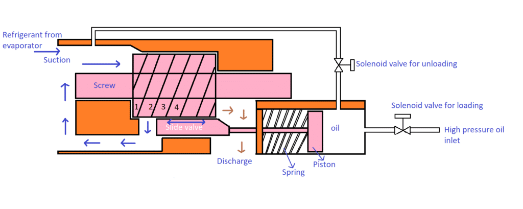
Working Principle of Slide valve for Capacity Control in Refrigerant Screw Compressors
If the slide valve moves towards the suction, the compressor will function at full load similarly if the slide valve moves towards the discharge, the compressor will function at part load. Actually, by moving the slide valve, the initiation of the compression process is altered. When the slide valve is completely moved towards suction, the compression of refrigerant gas starts from position 1 as shown in the above figure. Similarly, under the part-load conditions, the slide valve shifts to position 3 or 4 depending on the loading condition. Now the refrigerant gets trapped between the lobes or in the flutes from position 3 or 4 and compression starts. The volume of gas trapped in the lobes and flutes at positions 1 and 2 get recirculated to suction without getting compressed as shown in the above figure. Therefore, the flow of refrigerant through the compressor is controlled. Though the part of the refrigerant recirculated back to the suction that results in the initiation of compression from position 3 or 4, the discharge pressure remains the same. As per the ideal gas law,
![]()
![]()
From the above equation, if the mass of refrigerant that has to be compressed is reduced due to recirculation, to maintain the constant discharge pressure P, the compression volume has to be reduced. The same thing happens when the slide valve moves axially. Yes, both the mass of refrigerant as well as the compression volume reduces due to the movement of the slide valve towards the discharge port.
The control valve is connected to a spring-assisted piston (as shown in the above figure) driven by a hydraulic force from the oil. The lube oil is used to actuate the piston. The microcontroller of the chiller gets feedback from the evaporator suction pressure sensor. If the heat load is high, the suction pressure will be high. Then the microcontroller sends the signal to the solenoid coil to load the compressor by injecting the high-pressure lube oil to the slide valve piston causing the slide valve to move towards the suction port. Thus, allowing more refrigerant to flow through the compressor to meet the load demand.
PV diagram of screw compressor with slide valve in action
The above-explained slide valve working principle can be represented in the following PV diagram thermodynamically.
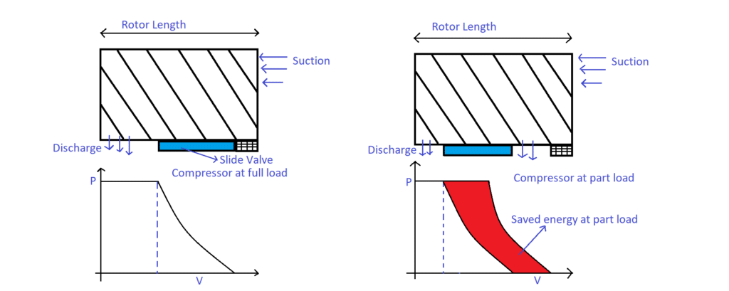
Note: Under the part load operation, the compression process starts after a certain delay. This results in energy saving which is shown as red coloured zone in the above figure.
Hence the slide valve assists in capacity control of a compressor that results in energy saving too.
