Table of Contents
Screw Compressor Working Principle
There are many types of screw compressors in terms of the number of screws used to compress the gas. If a screw compressor contains a single screw, it is called a single screw compressor; similarly, for two screws, it is called a twin-screw compressor. In general, to compress a gas, the twin-screw compressor is preferred widely. So, in this article, we will discuss twin-screw compressors. Here the rotor is also called screws because the helical-shaped grooves are wrapped around the rotor.
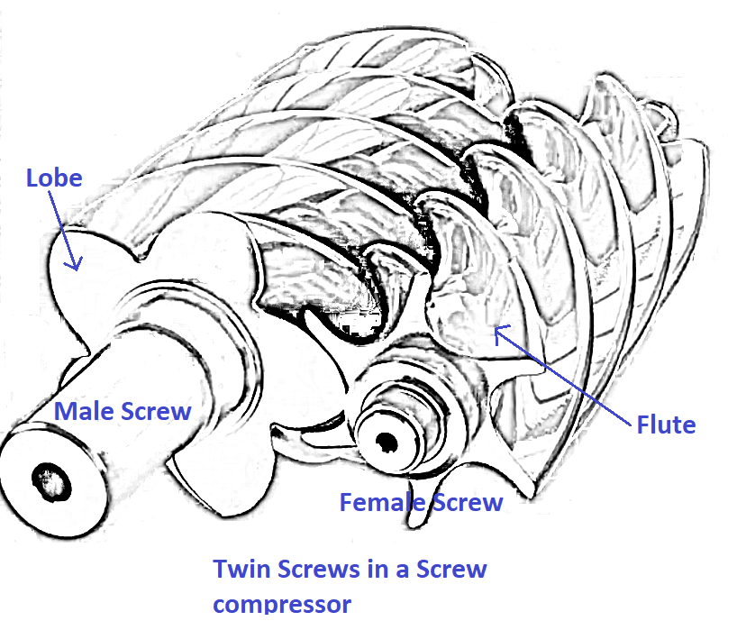
Gas in a screw compressor undergoes four sequential stages before getting compressed and discharged. They are
- Suction
- Transportation
- Compression
- Discharge
Suction
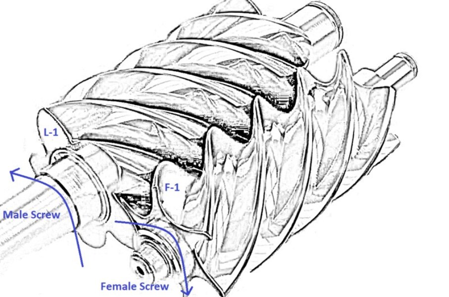
The rotor that has lobes is called the male rotor. Similarly, the rotor having the flutes is called the female rotor, as shown in the below figure.
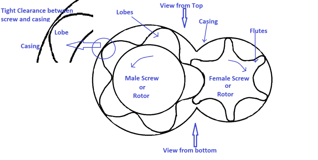
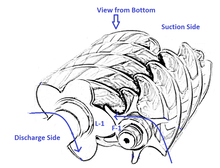
Casing encloses both the rotors. The male rotor is usually a driving rotor (connected to the motor) that drives a female rotor. Consider a case as shown in the above figure, the male rotor rotates in the anticlockwise direction, and the female rotor rotates in the clockwise direction. When the rotors rotate, male and female rotors un-meshes (i.e., both rotors disengage when seen from the top side), creating empty space between the rotors. Follow the path of lobe L-1 & flute F-1 to visualize the creation of empty space, as shown in the below figure. The following figure shows the initial positions of lobe L-1 and flute F-1.
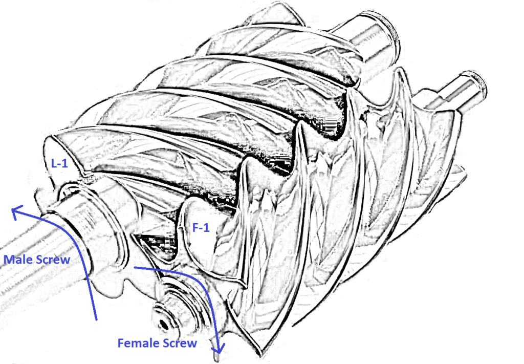
When the screws rotate, L-1 and F-1 un-meshes, and empty space is created as shown in the figure below.
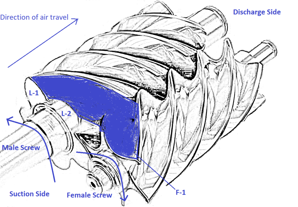
The gas (shown in blue colour in the above figure) fills in the gap between the lobes (L-1 & L-2) of the male screw and in the flute (F-1) of the female screw, as shown in the above figure. But do not forget that these rotors are enclosed in a casing with tight clearance between the casing and the rotors. Thus, suction is created.
Transportation
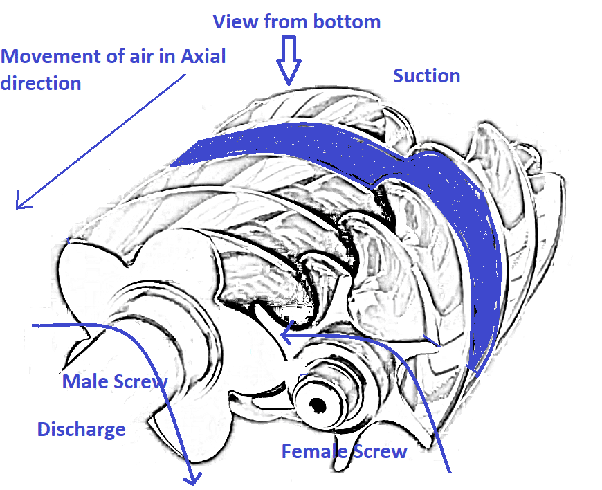
When the screw rotates, the trapped gas between the flutes & casing and lobes & casing gets transported to the bottom side, as shown below. The trapped gas moves in the axial direction towards the discharge port. The following figure represents the twin screws when viewed from the bottom side.
Compression
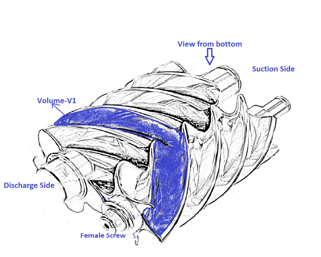
As the trapped gas moves in the axial direction, the volume of gas between lobes & flutes reduces, as shown in the following figure. As the screw rotates, the volume between the male & female screw and casing reduces from V1 to V2 with the same quantity of trapped gas as shown in the following figure.
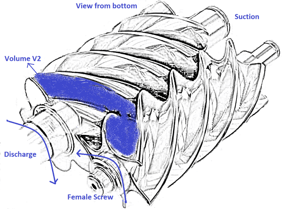
Thus, the volume reduces and pressure increases with the same quantity of trapped gas. One may have doubt that, because of this high pressure, gas can go back to the suction, but due to the gradual engagement of screws (i.e., metal to metal contact between lobes & flutes in case of oil-lubricated screw compressor gas cannot go back through the helical path and also due to tight clearance between the screw and the casing as shown in figure 2 gas cannot be leaked through it. Hence, the gas is trapped between the rotors & casing without going backwards. Therefore, it is called a positive displacement type compressor.
Discharge
Lobe can be treated as a piston and the flute can be treated as a cylinder. Finally, lobe L-1 at the discharge side pushes away the pressurized trapped gas from the screws to the discharge port as shown in the figure below.
Application of Screw Compressors
A screw compressor is preferred widely due to less maintenance than a reciprocating compressor because the number of rotating parts is less. The only rotating parts are screws and bearings. So, a smaller number of parts, lower the unbalance resulting in less vibration and maintenance. Refrigerating industry prefers a screw compressor as a refrigerant compressor to compress the gas.
Types of Screw Compressors based on lubrication system
There are two types of screw compressors based on their lubrication system.
Dry or oil-free lubrication screw compressor
The metal-to-metal contact between the male and female screw is avoided by maintaining the minute clearance between the two screws. Since there is no contact between the two rotors, a timing gear is mounted on both rotors so that the male rotor drives the female rotor using a gear drive. Of course, the Oil pump will lubricate the gear drive and the bearings on the rotors except for the screws. This type of system is called oil-free because the gas getting compressed between the screws is free from the oil since there is no lubrication between the rotors. This type of screw compressor is preferred when there is a stringent requirement for compressed gas quality.
Drawbacks of an oil-free screw compressor
Because of minute clearance between the male and female screw, compressed gas leaks through it and reaches the suction port (i.e., low-pressure side). Thus, the compressor efficiency reduces, and it can be avoided by increasing the rotating speed of rotors using high-speed motors. When the screws rotate faster, compressed gas does not find sufficient time to leak through the clearance between the rotors. But as compared to the oil-injected screw compressors, its efficiency is relatively low.
Wet or oil lubricated screw compressor
The male rotor touches the female rotor, and there is no need for timing gears. Oil pump or pressure difference between suction and discharge (in case of pumpless compressors) will lubricate both the rotors with the help of oil. The oil in the screw compressor has three functions to perform. They are,
- Avoiding friction and ensuring the smooth rotation of screws.
- Seals the gap between screws and casing near the discharge port.
- Cools the screws by taking away the heat due to gas compression.
